Hello and welcome to our first blog covering the progress of ‘Project Harrier’! As the title suggests, we have begun developing a new state-of-the-art 1:32 Hawker Siddeley Harrier model kit for release in Autumn 2027.
Rather than design the kit and begin tooling before announcing to the public, we wanted to do something slightly different: bring you along on the development journey and give you a
behind-the-scenes look at the processes we go through to deliver a new kit. To that end, we’ll be providing monthly updates using a YouTube video series, blogs such as this one, plus occasional updates via social media and model shows.
The blogs and videos themselves will be created by the development team working on the project, so you are hearing it directly from the horse’s mouth!

Progress to Date
We’ve been eager to announce this project as early as possible to ensure that you get a front-row seat for the entire project; however, to ensure we actually have something to show you at the outset, the team began design work in late March. This involves a lot of setup work, such as aligning scans and creating the cross-sectional planes that the designer uses to create the ‘skeleton’ model. Think of this step as the foundations of a model kit; any mistakes/errors at this point will cause the designer headaches further down the road, so it’s important to get this right from the outset!
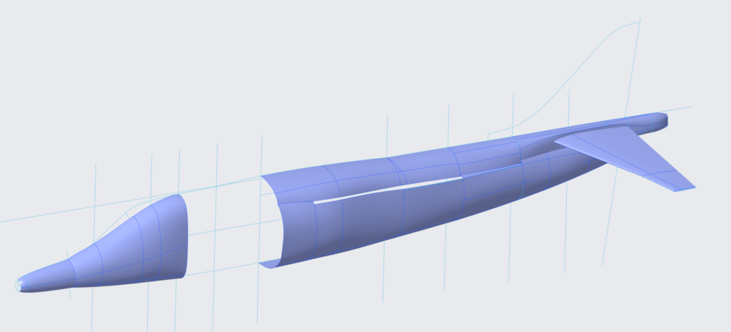
Figure 1 : Initial Skeleton model
Although it may not look like much, the skeleton model is a key stage in the design process. The designer uses it to flesh out the key geometry of the aircraft using sketches and surface modelling before eventually solidifying the surfaces, adding detail and splitting into parts.
In addition to the Harrier, we plan to tool a separate engine and display trolley for inclusion with the kit. This meant a tricky decision for us: do we design the engine so that it can also fit within the jet? You may be saying “Of course! Why wouldn’t you?!” but this would mean that the engine would need to be under-scale to fit within the fuselage (due to wall thicknesses) and risk looking out of proportion when displayed externally. We therefore decided to design the engine for external display only, with visible parts of the engine e.g. fan blades inside the air intakes designed as separate pieces for use in the airframe model.
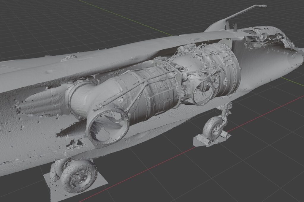
Figure 2 : Harrier scan cross-sectioned with Pegasus scan placed inside.
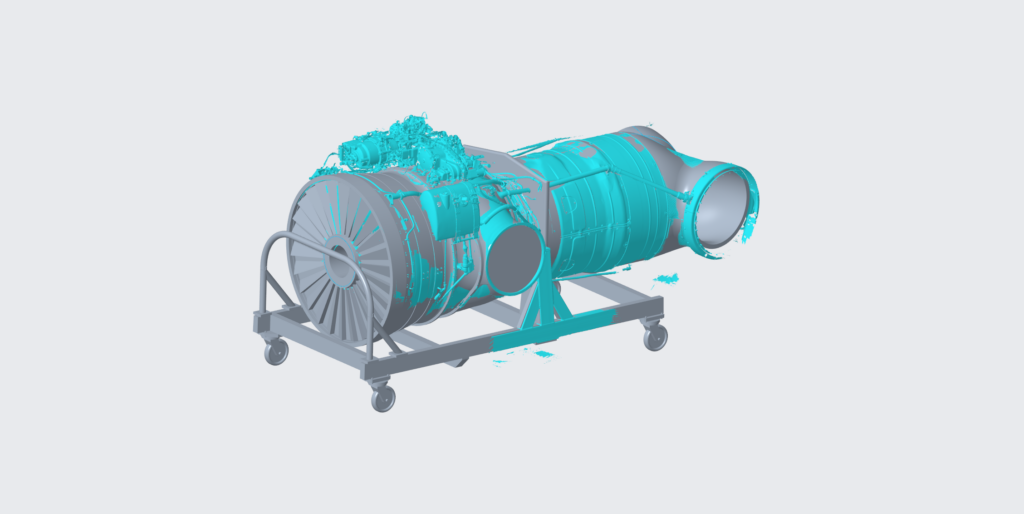
Figure 3 : Scan and initial design work overlayed.
Research to Date
Before the team even opened their CAD software to start design, we had to first gather a detailed research pack and set out a clear scope for the project e.g. versions to be designed, level of detail, optional parts, etc. To gather this research, there is an intense period of learning for the product manager who must get up to speed on the subject to best plot a course of action. In this case, we knew production drawings were unlikely to be a viable route and therefore 3D scanning, photography and good old measuring sticks were to be the way forward for obtaining shape data.
The first stop on our research trip was RAF Wittering, specifically their Heritage Centre. We decided that this was the ideal place for getting the greatest amount of information without needing to travel the length and breadth of the UK! Some of you may have seen a rumour that we had visited Wittering; it turns out nobody is safe from the Britmodeller Rumourmonger, even on an RAF base! So, I can indeed confirm that was us way back at the beginning of 2025.
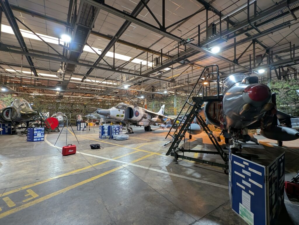
Figure 4 : Inside RAF Wittering’s Heritage Centre
Wittering offered the perfect place to capture the GR.3, plus the trainer versions and a P.1127 (RAF), along with a whole host of underwing stores. Now, before anybody writes in to tell us, we are aware that the P.1127 (RAF) is not representative of a GR.1, even if they look similar. One thing you learn early on when researching is to never trust a prototype; you’ll notice that the initial CAD work has been completed with the GR.3 as the core for this reason. The P.1127 (RAF) 3D scan will be used to ensure we get the GR.1 nose and tail correct.
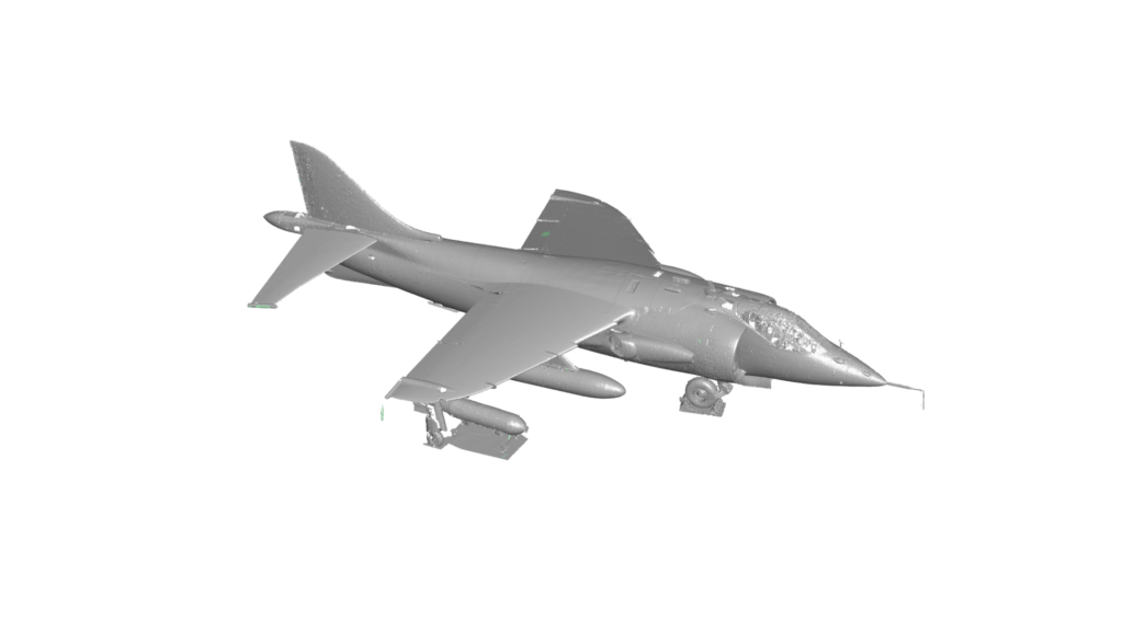
Figure 5 : 3D Scan of the P.1127 (RAF)
Following our visit to Wittering, the project was paused for a time whilst we finished off the 2025 range and waited for the design team to become available once again. Once the team was ready to commence, they were briefed on the Harrier and our existing research material and left to their own devices for a couple of weeks.
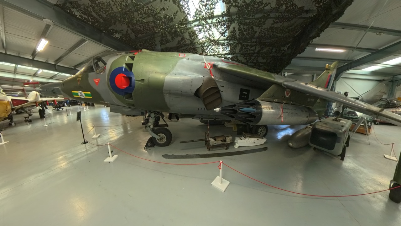
We soon set back out on the road to visit another airframe to give the designers an appreciation for the jet and the complexity of its shape. This time, we visited our old friends at the Gatwick Aviation Museum, who kindly let us inspect their Harrier, gathering various measurements and photos to aid the design process. Whilst these trips take time out of a designer’s schedule, they often help to speed up the process and lead to a far more accurate model.

Figure 6 : Harrier GR.3 at Gatwick Aviation Museum.
A few weeks later, we were back at Gatwick to do some further scanning and photos, this time focusing on the engine and cockpit. For the Pegasus engine, we used a specialist 3D scanner that can capture the finest of details down to 0.1mm to ensure we get everything correct. We also used it to partially scan the forward wheel bay and ejection seat.
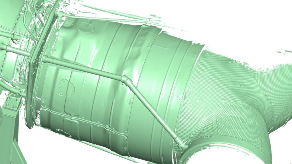
Figure 7 : Partial scan of the Pegasus engine showing the detail captured.
Gatwick proved to be the best place to conduct our further research, as the seat was displayed outside the jet, allowing us to get images of the cockpit floor which otherwise would be obscured and a bit of guesswork by the designer would be required. This meant we could get 1000’s of images of the cockpit from all angles and create a 3D file using photogrammetry.
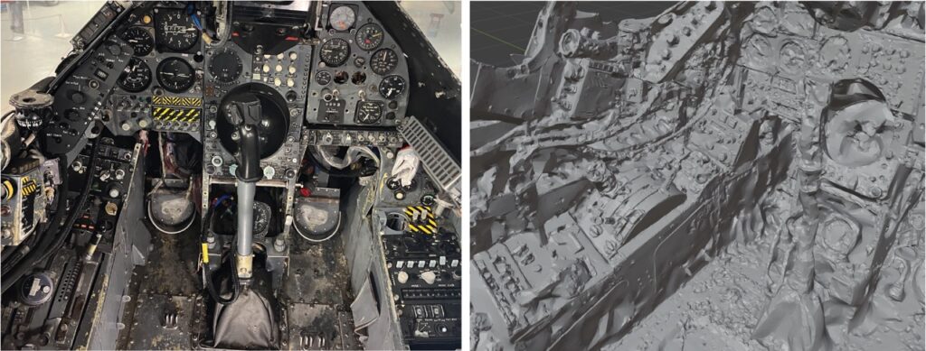
Figure 8 : Harrier GR.3 cockpit photo and photogrammetry file.
Whilst the file may look rather rough, this technique allows us to capture cockpit proportions quickly and easily with more accuracy than photos by themselves! However, the quality is nowhere near that of a dedicated 3D scanner, as you can see in the comparison of the forward wheel bay below:
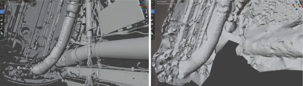
Figure 9 : Front wheel bay scan comparison. 3D scanner (left) and photogrammetry (right).
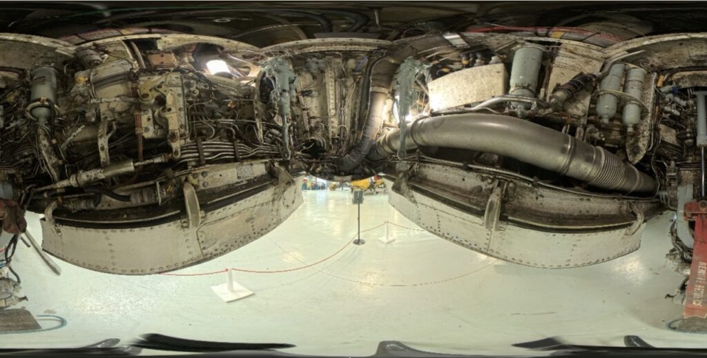
Figure 10 : Front wheel bay photo taken with 360 camera.
What Next?
Over the next month, the design team will continue their work, progressing the skeleton models, and we’ll post another update in early June. We sincerely hope that the news of a new large-scale Harrier family has you jumping for joy. If you have any suggestions for the product or how we can engage you throughout the whole development process, then please get in touch!
Finally, we would like to thank the RAF Wittering Heritage Centre and Gatwick Aviation Museum for their invaluable contribution to this project.
If you would like to share your knowledge about the Harrier or point out common pitfalls, please send an email to info.de@carrera-revell.com with the subject line „Project Harrier“. I will try my best to read them all and answer them if possible!
Kind Regards,
Luke