
Hello, and welcome to the fifth installment of our Project Harrier blog series! For those joining us for the first time, it’s worth reiterating what this is all about. We have begun developing a new 1:32 first-generation Harrier family, with the first boxing (comprising parts to build either an RAF GR.1 or GR.3) being released in Q3 2027.
Rather than design the kit and begin tooling before announcing to the public, we wanted to do something slightly different: bring you along on the development journey and give you a behind-the-scenes look at the processes we go through to deliver a new kit. To that end, we’ll be providing monthly updates using a YouTube video series, blogs such as this one, plus occasional updates via social media and model shows. The blogs and videos themselves will be created by the development team working on the project, so you’re hearing it directly from the horse’s mouth!
This month has seen our design team, Chris & Horatio, progress their respective elements of the design even further. We have reached a point where all parts are now created; this has allowed us to send the Harrier off for tooling quotation. Whilst we wait on that, we have a couple more weeks to fine-tune everything and adjust details where needed. Chris has spent the month applying finishing touches across the airframe, with surface detail now almost completely added and the finer details for each version worked out. Horatio made some final tweaks to the Pegasus engine and created the assemblies for all underwing stores before taking a much-needed holiday; as you read this, he’ll be back to work adding detail onto the parts ready for tooling.
Airframe Progress
Chris has been adding rivet/fastener detail across the airframe, with this now mostly done aside from a few areas. A lot of focus has been on the small parts that vary between versions, such as anti-collision beacons, aerials and the tail cones. This stage of the project requires a lot of back and forth between the designer, product manager and subject matter experts to ensure we include everything needed.
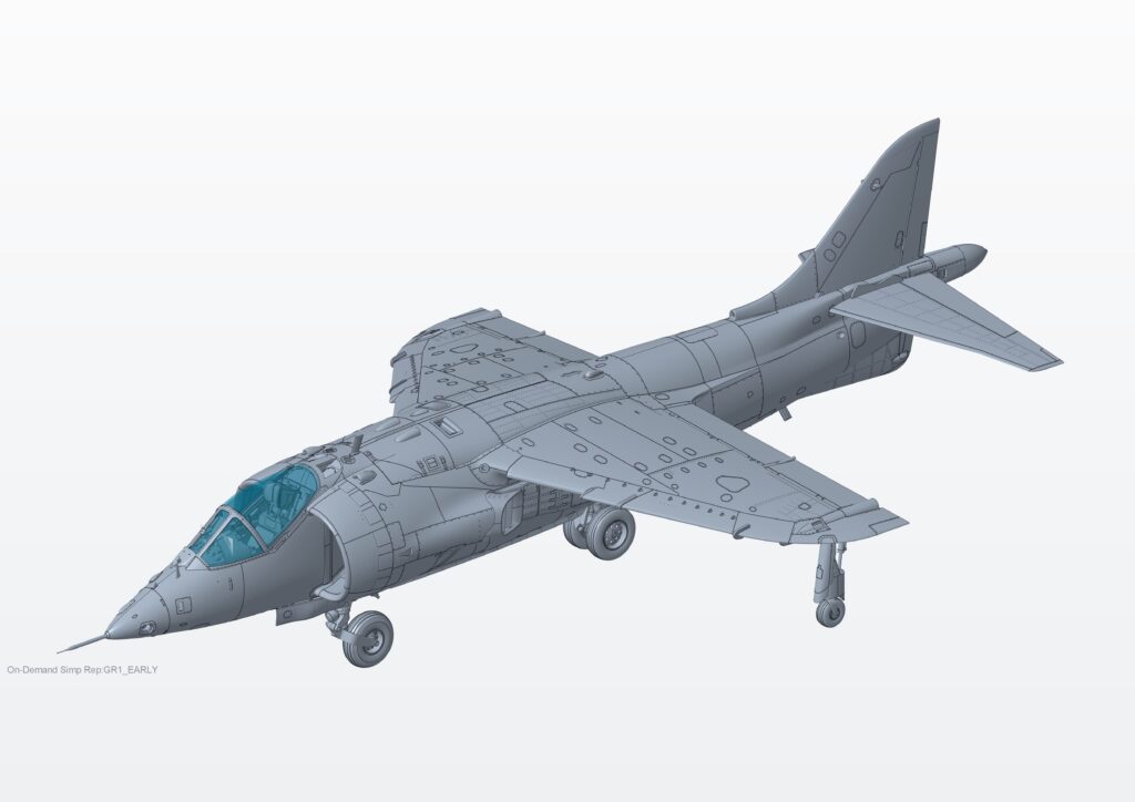
Figure 1: Airframe progress as it stands on 28/09/2026, top view of GR.1.
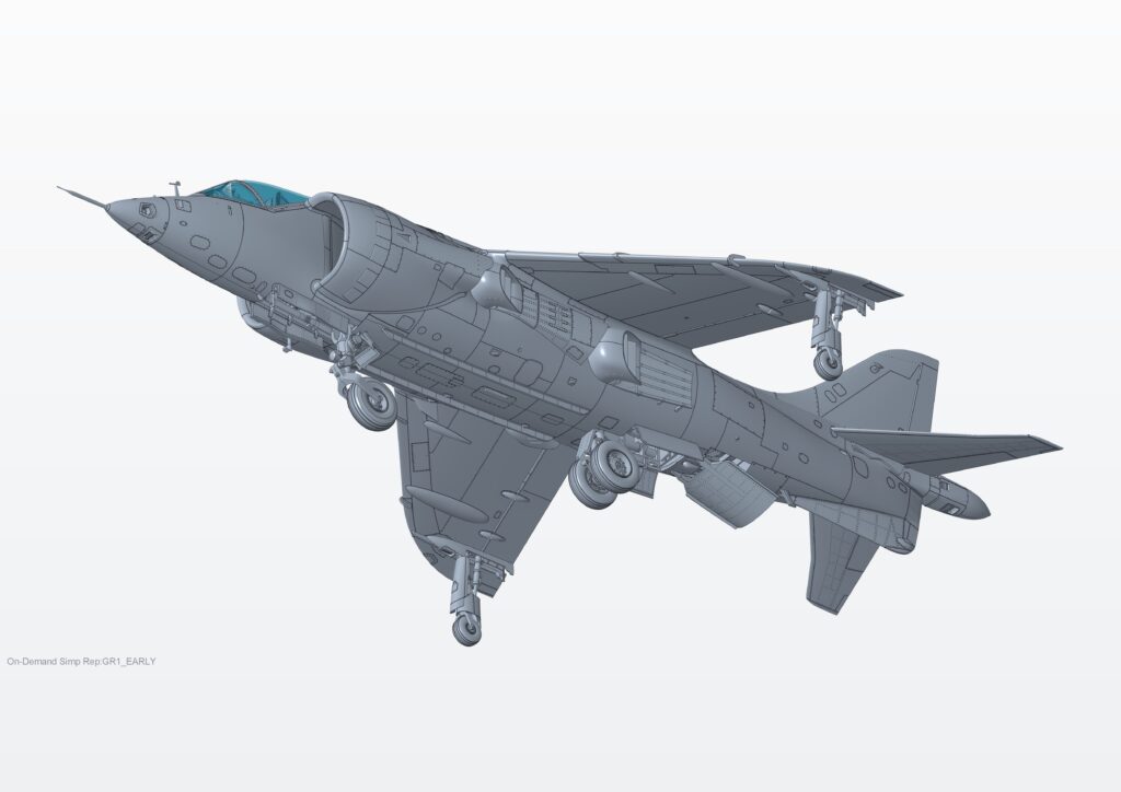
Figure 2: Airframe progress as it stands on 28/09/2026, underside view of GR.1.
Using 3D scans, photos and manuals, Chris has been fine-tuning all the surface detail and option parts, but after 6 months of staring at the screen, things are bound to slip through the cracks! Therefore, we always aim to have another two or three sets of eyes look over the model in a couple of rounds to ensure we minimise the chance of errors. These checks can focus on various aspects ranging from the configuration of parts for each version all the way down to individual rivet location.
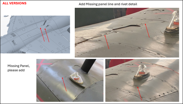
Figure 3: Example of some of the comments that arise during the final check.
Surface detail on the Harrier has proved tricky; generally speaking, the airframe is quite smooth and without too many obvious fasteners. There is a mix of recessed and raised ‘rivets’ across the model as well as lapped panels where appropriate to enhance the realism.
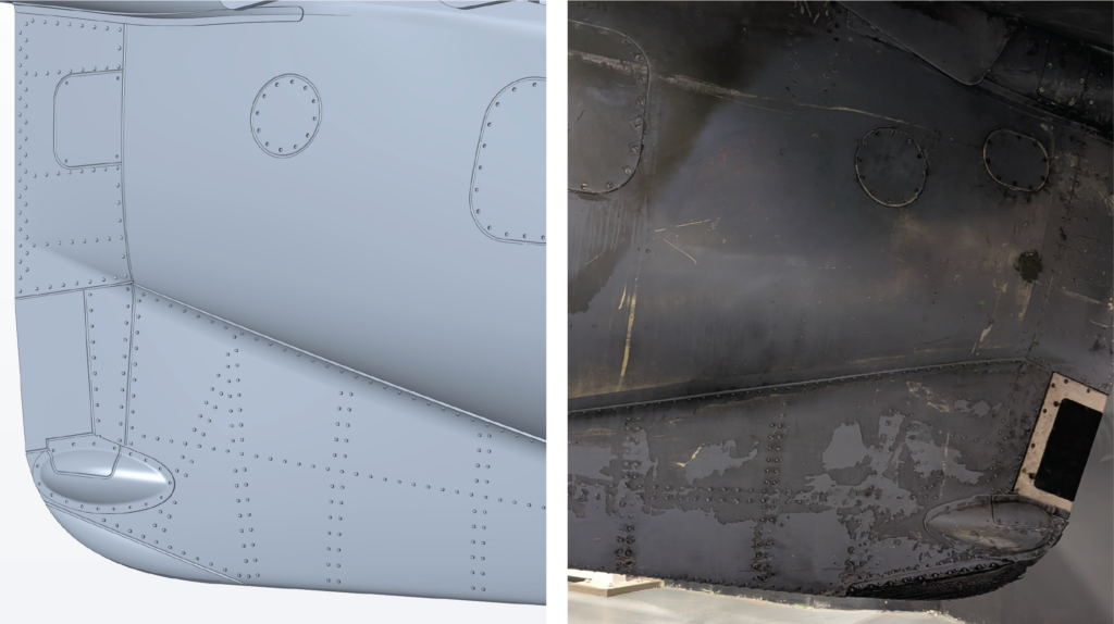
Figure 4: Ventral fin area of the Harrier, displaying the various types of surface detail added.
Many of the flush rivets were not easily visible when visiting
museum aircraft; we used a range of images taken from when jets were in-service plus various examples from museums and added the areas where rivets were most commonly seen, such as the top and outer reaches of the wings.
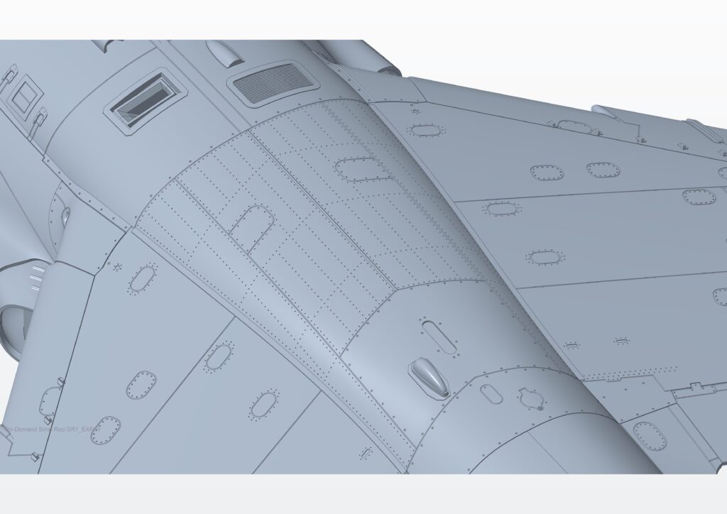
Figure 5: Flush rivets atop the central wing section of the Harrier.
One thing that came up when checking through all the surface detail was the rendering of the radar altimeters on the ventral fin. We had fallen into the trap of copying museum aircraft and subconsciously thinking that what is now must have always been! Almost all museum aircraft we visited had the altimeters on the fin, and although we knew they had been added later in the Harrier’s life, we assumed the outer panel had always been there, but this was not the case.
We had initially planned to have two infill pieces (one with and one without the altimeters); however, we realised this would compromise almost all pre-1988 schemes and therefore elected to change direction. We decided that since the majority of aircraft would not have them fitted, we would show the ventral fin without them fitted but add a cutline on the inner face and provide an infill part for those wanting to create a Harrier with the altimeters fitted. Just one example of some of the design/tooling decisions we have to make throughout a project as complex as the Harrier!
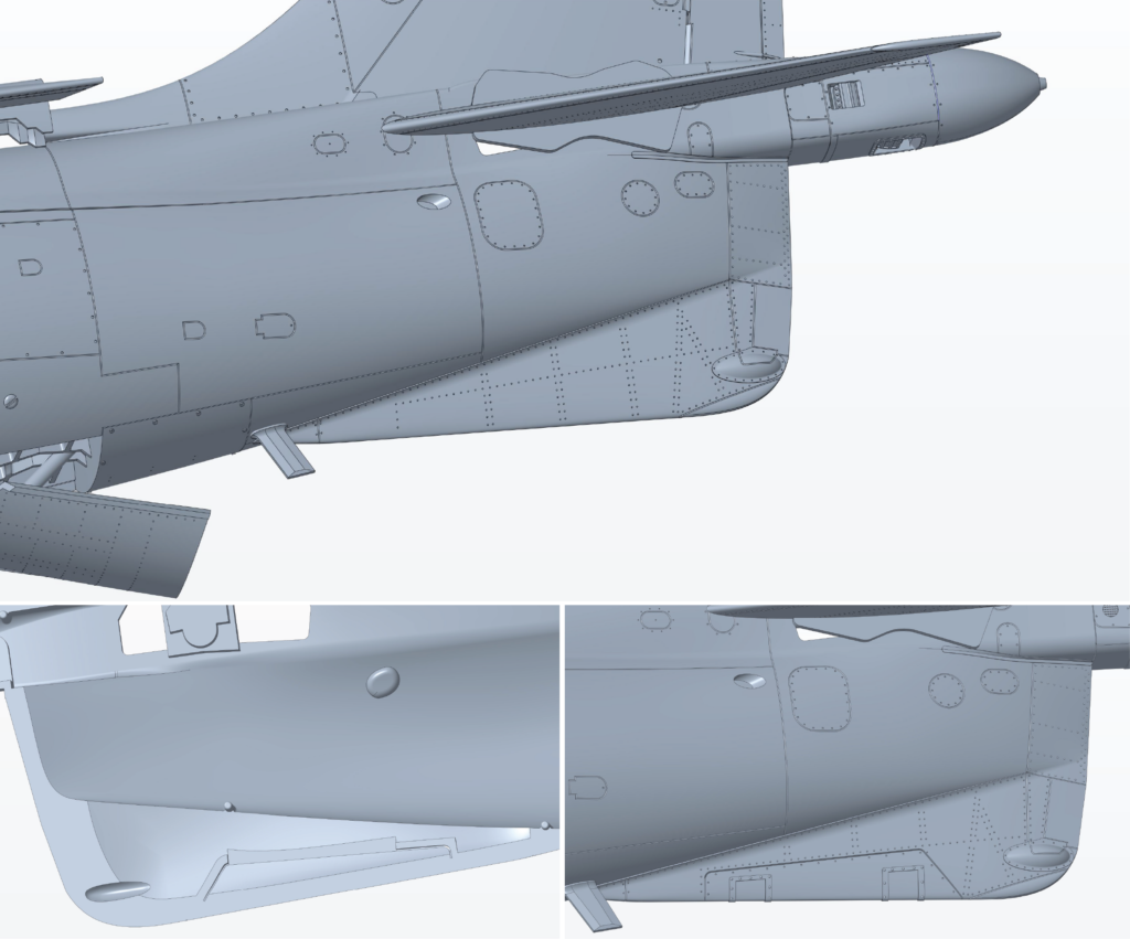
Figure 6: Images showing the moulded-on detail for the ventral fin, the inner cut line & the radar altimeter infill piece.
Chris also spent part of the month working on the undercarriage, specifically the versions of the parts needed to show the Harrier whilst hovering. This is something the team has not encountered before, as usually the configurations offered are simply ‘static/on the ground’ or ‘in-flight’, but the Harrier’s party trick could not be ignored, and so we felt it only right that we offer the parts for anybody wanting to show their model hovering. On a related note, we are currently looking into ways to help people show the model in-flight or hovering by offering a 3D-printable stand that could be printed at home or ordered from a supplier; early days yet but we have 12 months until the kit hits the market, so we have a bit of time. What do you think would work best?
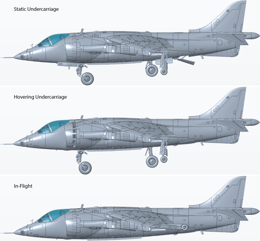
Figure 7: Images showing the various undercarriage configurations.
Pilot Figure
Amanda has finished the design for the pilot figure and is now working on creating the modified version for injection moulding and inclusion within the main tools. This process involves splitting the figure up into various parts (head, torso, arms and legs) and changing some of the surfaces to ensure the parts can successfully be moulded – this process is currently ongoing!
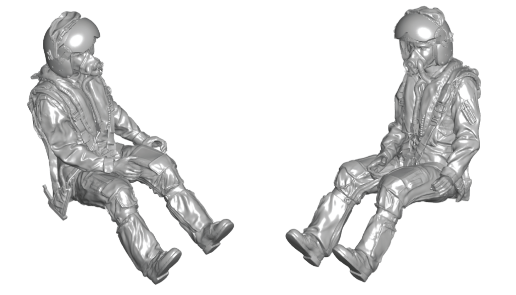
Figure 8: Final pilot figure sculpt before being optimised for injection moulding. We plan to offer this version as a downloadable file for those able to print at home.
Before we could call the pilot figure complete, I thought it best to check that the figure integrated well with Chris’ cockpit/airframe. This is when we discovered an issue that was of our own making. Chris had sent Amanda the CAD of the seat/cockpit at an early stage, but we had not included the canopy. Fast forward a couple of months, and when we added the figure to the assembly model, we had a slight clash with the canopy, mainly due to the difference in thickness on a scale model compared to the real thing. Luckily, we were able to reduce the pilot figure’s height by about 1.5mm (spread across the helmet, torso and bottom) to avoid a clash!
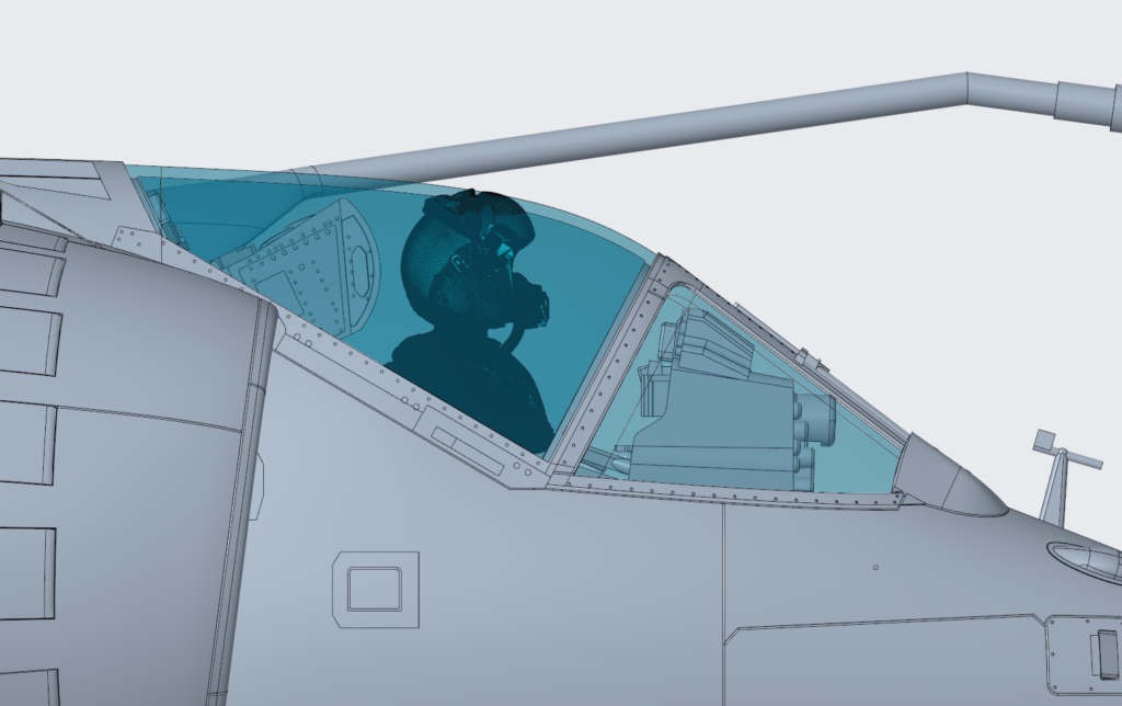
Figure 9: Image showing the clash between the pilot’s helmet and the canopy.
Creating the 3D printable version and being confident no more shape/equipment changes are required before proceeding is crucial to minimise the work then needed to create the injection mouldable version of the figure. Amanda has recently created the two head parts that will be used in the kit (visor up & visor down) with the correct draft angles; I hope you agree they look mightily impressive.
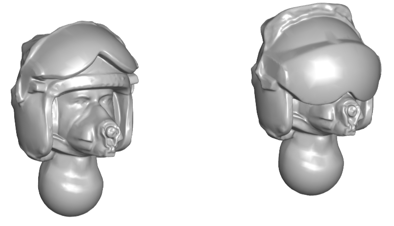
Figure 10: Pilot heads optimised for injection moulding.
Engine Progress
As mentioned in the last update, the Pegasus engine is now complete apart from a bit of tinkering as a result of a test 3D print to check assembly.
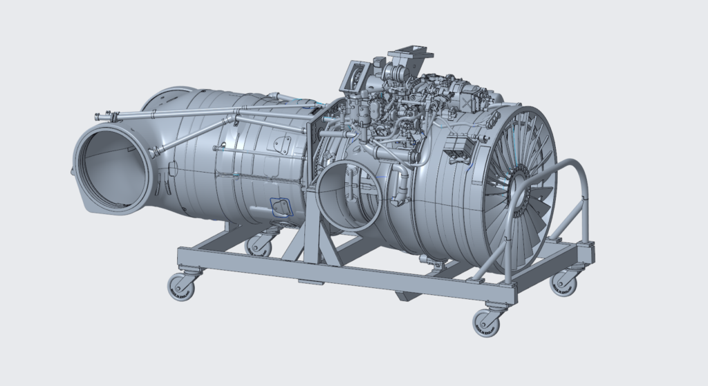
Figure 11: Pegasus Mk.103 design mounted to its display trolley.
We’ve done a lot of checking to make sure we’ve accurately portrayed the Mk.103 (Pegasus 11), with there being quite a few small changes required. As with the airframe, we always try to have multiple people look over the design to ensure no errors slip through the net. A lot of the points raised have often already been considered by the designer, but it is always good to take a second look and question decisions made.
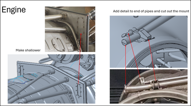
Figure 12: Example of a slide produced as part of the checking process.
One of the small changes made in the past month has been the addition of some reinforcement for the pipes. A tab has been added to connect two pipes to reduce the chance of them breaking whilst in the box; the modeller simply has to remove this piece when assembling. However, being modellers ourselves, we know how easy it is to forget/overlook this sort of thing, we therefore add hints/tips to reduce the chance of errors. In this case, we added the text ‘Remove’ to the part.
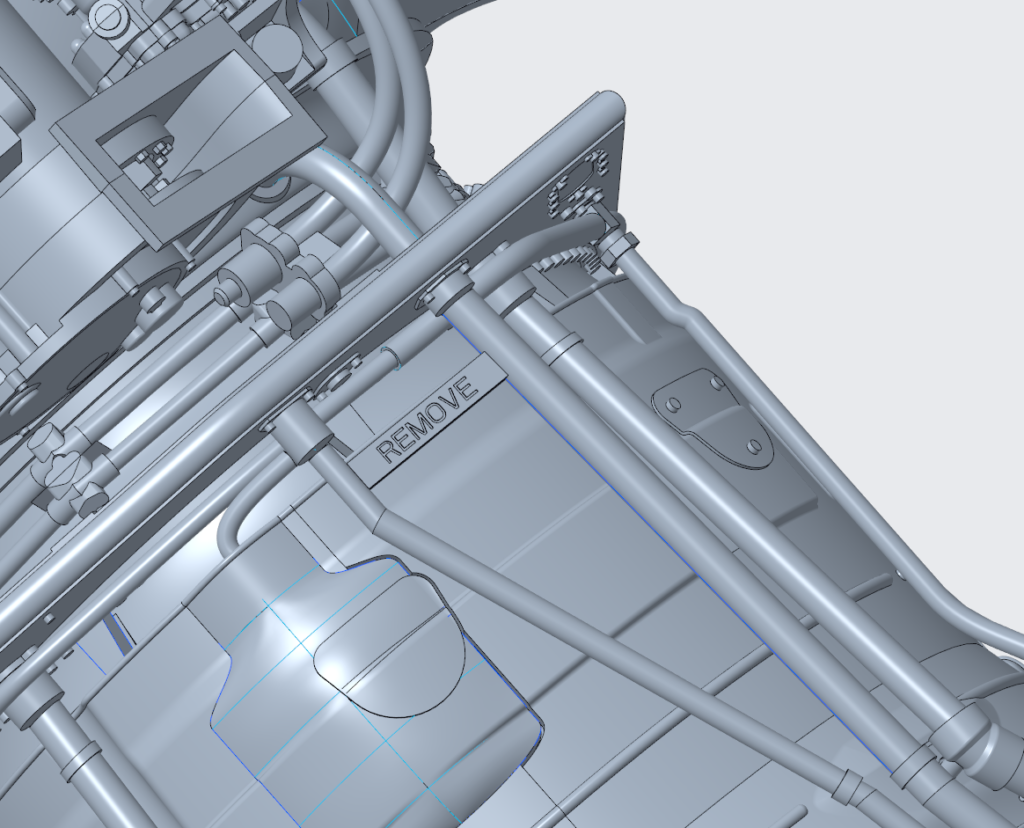
Figure 13: Strengthening tab with a helpful bit of text to remind the modeller to remove the piece.
Underwing Stores
Our main focus between the blog being written and going live will now be finalising the underwing stores. Horatio got all items created and split into the correct number of parts before departing on a well-deserved holiday; this allowed us to proceed with getting tooling quotations from our suppliers and reduce downtime. As you can see from the image below, this means the basic shape is there but lacking a lot of the detail.
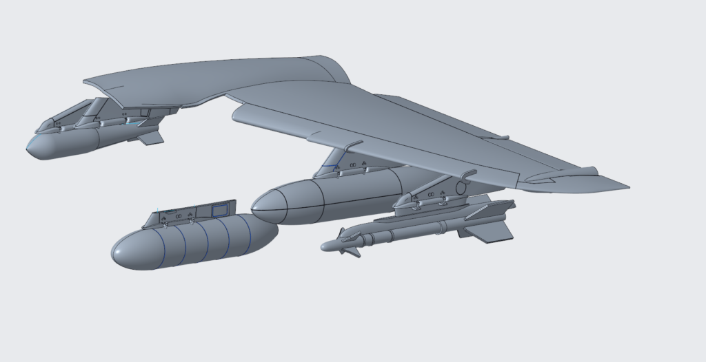
Figure 14: Basic design of the pylons and underwing stores.
We will spend the next two weeks working item by item, adding surface detail, checking and reworking until each item is complete. We’ve had a few people ask what we’ll be including in the kit in terms of weapon/stores; at this time we are planning the following:
1 x Harrier Recce Pod (AKA Vinten pod, although Vinten have confirmed it was in fact designed and developed by Hawker Siddeley)
2 x Matra 155 Rocket Pods (With & without frangible cover on cone)
2 x AIM-9 (G & L variant to be included in the kit).
2 x 1000lb GP Bombs (Mk.114 tail & Mk.117 tail options)
2 x BL755’s
2 x 100 Gallon Tanks (Metal and Phenolic Asbestos versions)
These items are subject to change, mainly if we need to reduce the tooling cost slightly! However, I’m hopeful that it will remain the same.
“Your Name Here” Competition
As part of our ongoing partnership with the modelling charity Models for Heroes, we have come together to launch a competition to raise funds to help them with the amazing work they do. You can find out more about Models for Heroes here: https://www.modelsforheroes.org.uk/
The prize? One lucky winner will have their name added to the Harrier decal sheet in the form of a pilot/crew name and receive a copy of the kit when released in Q3 2027. Now, it won’t just be added to one decal sheet; the winner’s name will feature on the entire production run!
For more details and to enter, please use this link: https://raffall.com/425233/enter-raffle-to-win-your-name-on-the-new-132-revell-harrier-gr1gr3-hosted-by-modelsforheroes
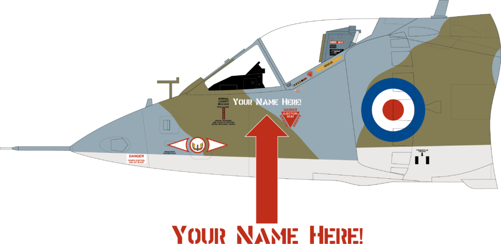
Figure 15: Illustration showing where your name could end up!
YouTube
As with every update, we have also recorded and released a video update covering much of the same content but with a few differences. So, if you simply can’t get enough of us wittering on about Harrier (pun intended!), then please check the YouTube video out:
What Next?
Over the next month, the design team will be fine-tuning all parts whilst we liaise with the tool shop regarding frame layouts. We’ll be posting another update slightly earlier than usual to avoid clashing with Scale Model World 2026, meaning the next update will be in late October (Friday 31st). Chris will mainly be focusing on adding rivets to the airframe and sorting out option parts such as aerials and other small details. Horatio will be finalising surface detail for the underwing stores, sending each one for checking by myself and other subject matter experts before we commit them to steel.
In our last update, we mentioned that we were hoping to post a series of screenshots of the near-final design for you to look over and provide comments. Those screenshots can be found here:
https://imageshack.com/a/ox887/1
We’d appreciate any comments you have, but be quick; we need to finalise the design before tooling starts in November!
If you would like to share your knowledge about the Harrier or point out common pitfalls, please send an email to info.de@carrera-revell.com with the subject line “Project Harrier”. I will try my best to read them all and answer them if possible!
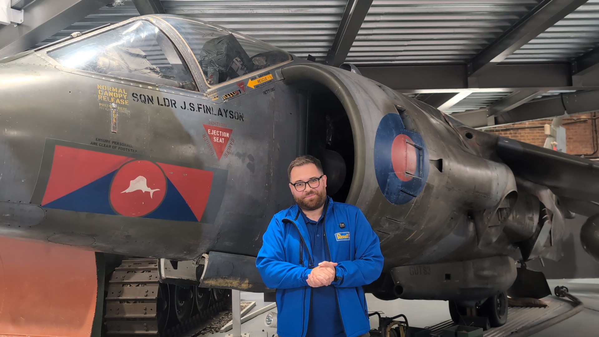
Thank you to the Royal Engineers Museum for allowing us to visit earlier this month to record the video update.
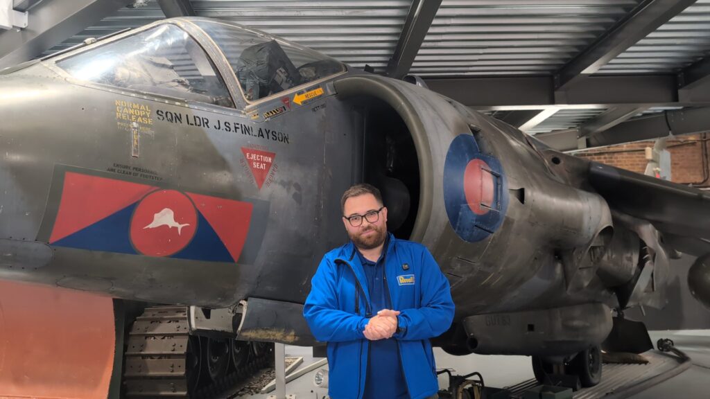
Figure 16: Author in front of XZ964 at the Royal Engineers Museum, Gillingham.
As in previous months, Nick Greenall has been providing invaluable support to the whole team, and we count ourselves lucky to have his expertise to rely upon. Thank you, Nick!
Until next time!
Luke