
Hello, and welcome to the fifth instalment of our Project Harrier blog series! For those joining us for the first time, it’s worth reiterating what this is all about. We have begun developing a new 1:32 first-generation Harrier family, with the first boxing (comprising parts to build either an RAF GR.1 or GR.3) being released in Q3 2027.
Rather than design the kit and begin tooling before announcing to the public, we wanted to do something slightly different: bring you along on the development journey and give you a behind-the-scenes look at the processes we go through to deliver a new kit. To that end, we’ll be providing monthly updates using a YouTube video series, blogs such as this one, plus occasional updates via social media and model shows. The blogs and videos themselves will be created by the development team working on the project, so you’re hearing it directly from the horse’s mouth!
This month has seen our design team, Chris & Horatio, progress their respective elements of the design even further. Chris has begun the process of adding panel lines across the airframe and generally enhancing the detail offered in areas such as the wheel bays. By the time you read this, Horatio will have completed the Pegasus engine. When we checked in with him, he was a mere day or two away from having the design finished.
Airframe Progress
Chris has finished splitting the main components into individual parts and has begun adding detail in the form of panel lines. We’re also now focusing on smaller details such as aerials, probes and vents.
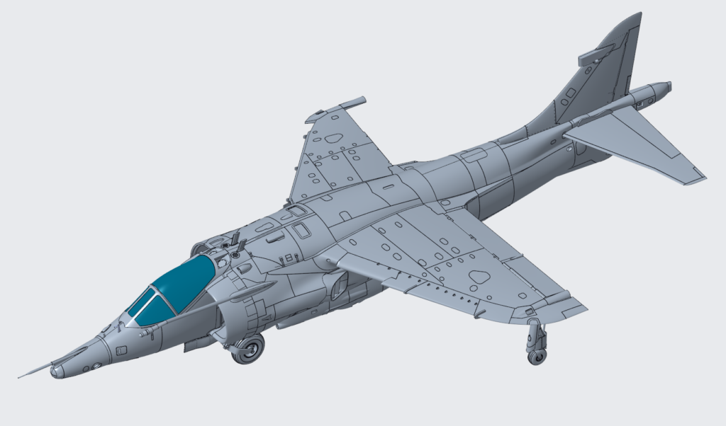
Figure 1: Airframe progress as it stands on 28/08/2026, top view.
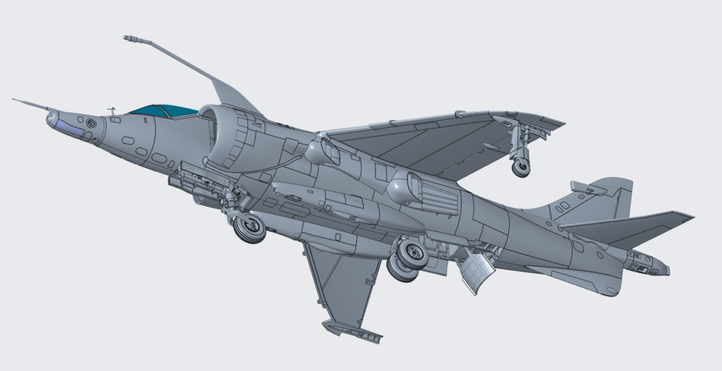
Figure 2: Airframe progress as it stands on 04/08/2026, underside view.
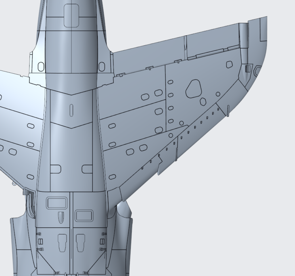
Figure 3: A closer look at the panel lines added to the top of the fuselage and wing.
Chris has also been working on some option parts, and it dawned on me that we’ve neglected to show the GR.1 in any detail up until this point! Now, many people assume the difference between a GR.1 and GR.3 is the nose cone, but it’s actually the engine that was fitted that leads to the change of mark. That being said, the angular/pointy nose is commonly associated with the GR.1, and Chris has spent a bit of time working on this.
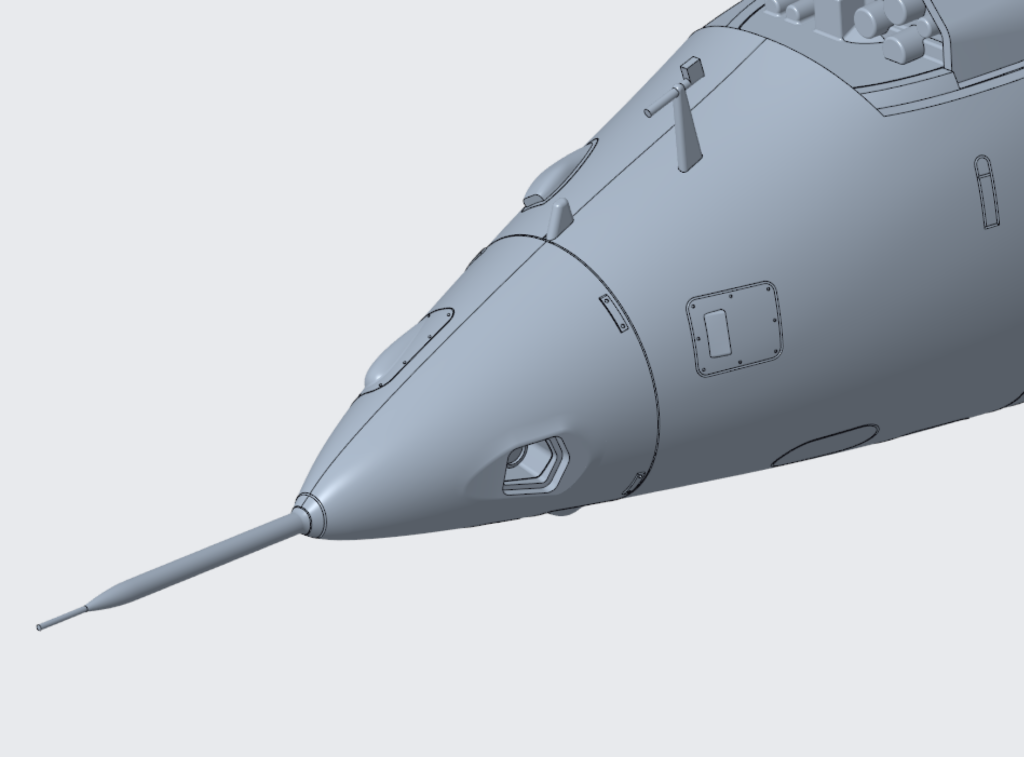
Figure 4: GR.1 nose cone, I personally prefer the look of this compared to the GR.3, what do you think?
Another difference between the GR.1 and GR.3 is the tail fin; again, most people assume the difference is simply the RWR fairing, but in fact the GR.1 fin is shorter. This is something I highlighted during a recent design review, and as a result the shorter fin is currently being worked on.
Work on the undercarriage is continuing with the main wheels and outriggers now completed; the next month will see Chris tackle the ‘Weight off’ versions for use when displaying the Harrier hovering, not something we have to worry about on most models! Due to the fact that we need to design two of each part to account for ‘on the ground’ and ‘hovering’, we’ve decided not to add additional legs featuring the tie-down rings fitted to Falklands aircraft; this is mainly a part count issue for us, and we have to draw a line somewhere.
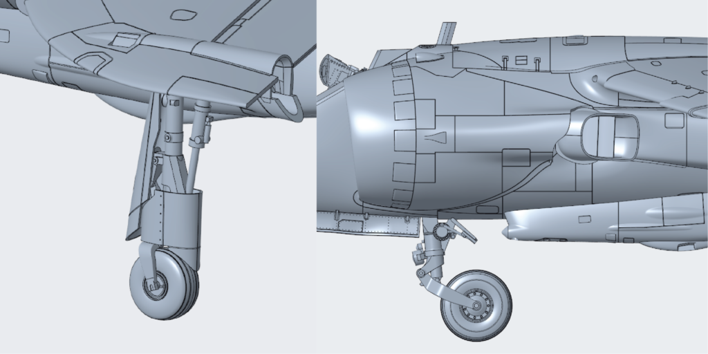
Figure 5: Outrigger leg/wheel (left) & front leg/wheel (right).
Last month we showed some of the work that was going on within the undercarriage bays; detail was being added, but we always need to be careful about the photos/research that we trust and an eagle-eyed reader was able to point out a mistake we had made! When visiting Gatwick to photograph their jet, we realised that their forward gear bay was missing some panels, leading us to use an image found on the internet to fill the gap. However, thanks to our reader, it was noticed that the image was actually taken from a Harrier II rather than a first-generation Harrier and was therefore wrong, a near miss!
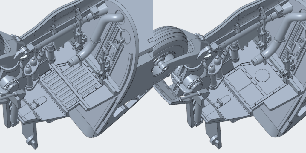
Figure 6: Incorrect top panels (left) & corrected top panels (right).
Pilot Figure
The pilot figure is getting a lot closer to being finished, the main figure has now been positioned and clothing added. Currently Amanda is designing it without compromise, but we’ll have to revisit at some point to make it mouldable; the natural folds of clothing often cause trouble when using a 2-part mould.
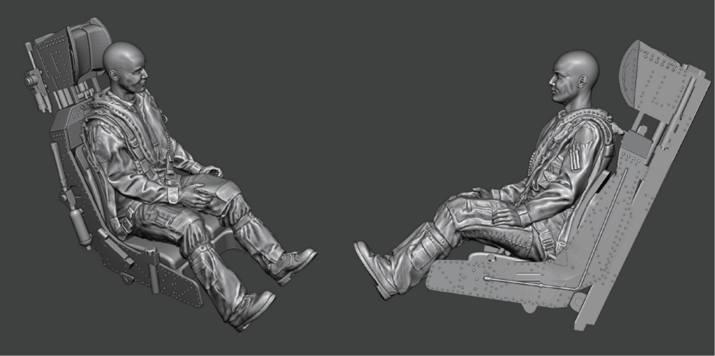
Figure 7: Pilot figure without helmet sat in the kit seat.
Partway through the figure design, we noticed that the seat that we had 3D scanned had actually been positioned at its lowest setting, meaning that the average-sized pilot would not fit comfortably. We therefore revisited the seat design and increased the distance between the main body of the seat and the headrest.
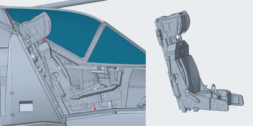
Figure 8: Original seat within the cockpit with arrows to show corrections needed, corrected seat on the right.
The pilot figure within the kit will be compromised slightly to allow for injection moulding. However, we also plan to offer a downloadable figure for 3D printing that has not been altered with injection moulding in mind for those that are able to make use of such a file.
Engine Progress
The Pegasus is now complete bar a few minor details and a bit of tweaking. I hope you agree it’s looking sufficiently busy! Horatio will be 3D printing this off shortly and optimising the design for buildability. We’ve agreed that reducing part count is not the focus, we can have lots of parts but none of them should be unnecessarily fiddly, we want you to enjoy the build after all!
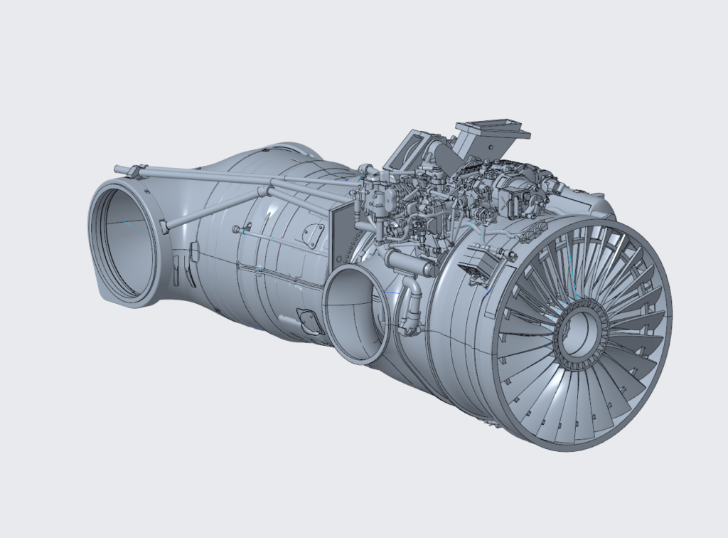
Figure 9: Pegasus Mk.103 design at 99% completion.
We’ve done a lot of checking to make sure we’ve accurately portrayed the Mk.103 (Pegasus 11) with there being quite a few small changes between the various Pegasus types. The most complex area has, of course, been in and around the accessory gearbox that sits atop the engine. This area houses the generators/alternator, fuel control system, nozzle control etc.
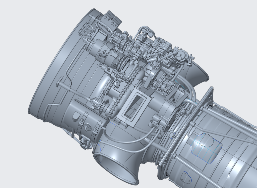
Figure 10: The accessory gearbox, fuel control system and other equipment that sits atop the engine.
Since last month, Horatio has added a lot of detail, but perhaps the biggest change is the addition of the Gas Turbine Starter. Using the photographs and 3D scan obtained at BDAC, Horatio was able to create a detailed rendition of this part complete with some of the internals that are visible on the real thing:
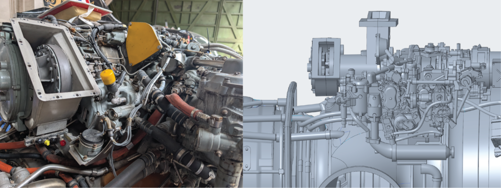
Figure 11: The Gas Turbine Starter fitted towards the back of the bulkhead.
We are working with our toolshop to understand the best way to apply the texture to the back of the engine. We had debated leaving it plain but this felt like a missed opportunity. Adding the texture in the computer software is possible, but the toolshop expressed concerns about their ability to apply it effectively. We therefore asked for their opinion, and they were able to supply a few pre-set textures that they feel confident they can apply, the image below being the best one. A bit more work is needed, but we are happy we can apply the texture effectively!
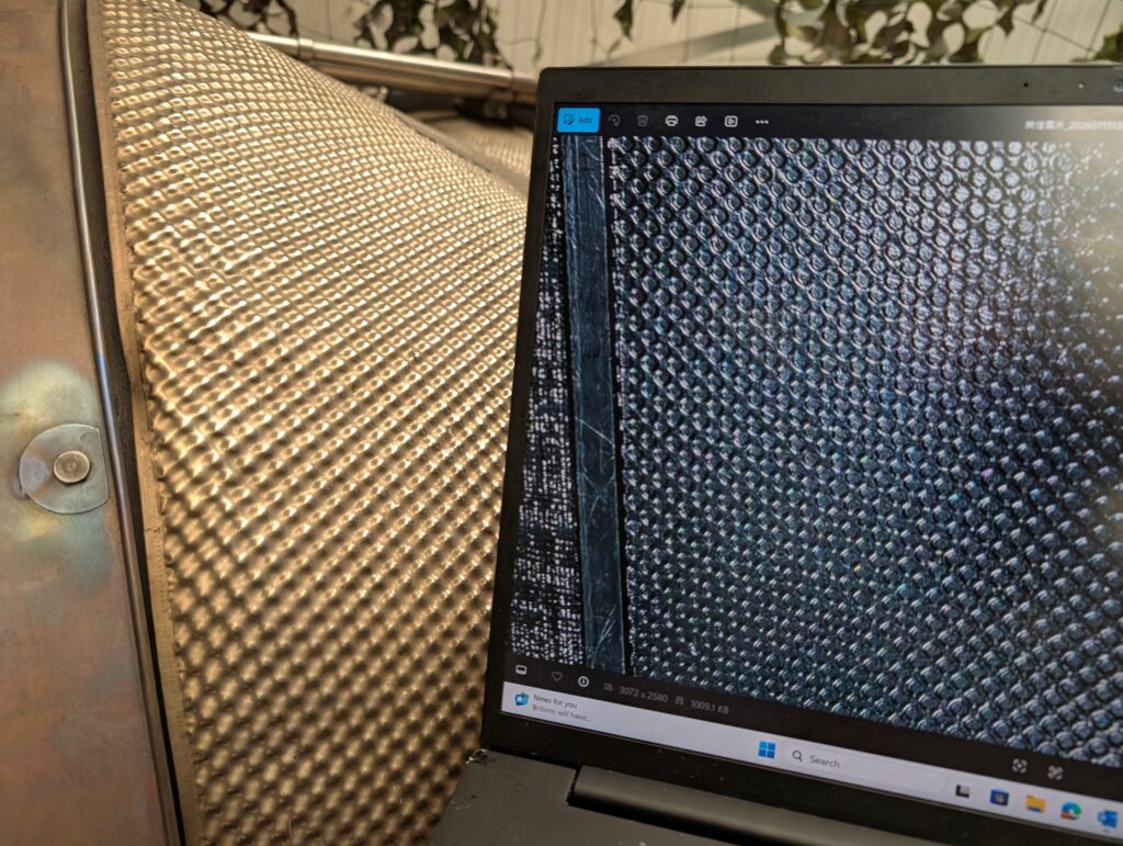
Figure 12: Proposed mould texture (on laptop screen) compared to the real texture.
Whilst Horatio has been working on the Pegasus Mk.103, I have been working to better understand the differences between that and the Mk.101/Mk.102. A quick recap: the Harrier GR.1 was fitted with the Mk.101, the Harrier GR.1A was fitted with the Mk.102, and the GR.3 was fitted with the Mk.103. As our first boxing covers the GR.1 and GR.3, I felt that we needed to at least understand the differences and do our best to accommodate them.
Images of the earlier Pegasus engines as fitted to the first RAF and USMC Harriers are hard to come by. Luckily, we have an original installation guide for the Pegasus 101 (Thanks to Mr Tim Perry), which has proved extremely useful. Now, most changes between the engines are internal and, as such, not worth worrying about in this case. However, there are some notable changes to the equipment fitted to the accessory gearbox.
Firstly, rather than a single 12 kVA generator, the Mk.101 was fitted with 2 x 4 kVA generators. If you look at a Mk.103 you’ll see a blanking plate where the second 4 kVA generator was originally mounted.
The installation manual was great for showing the general shape/size of these units, then we realised it actually featured a part drawing for them, which I admit I got far too excited about!
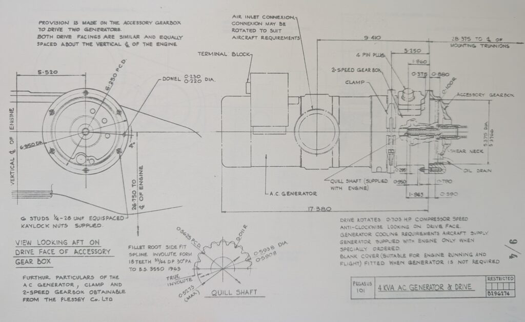
Figure 13: Technical drawing of the 4kVA generator used on the Pegasus Mk.101.
We then realised that we had a photograph from our visit to Aerospace Bristol a month previously that featured these exact generators:
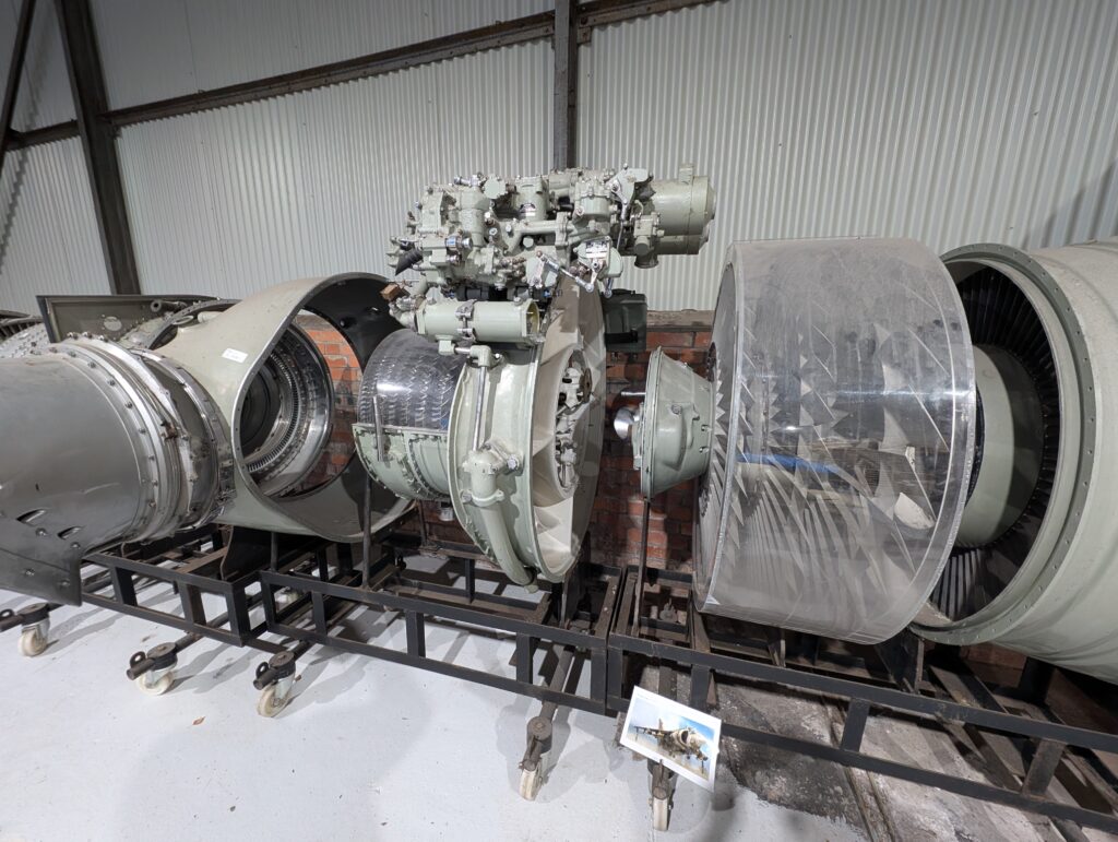
Figure 14: Disassembled early Pegasus engine on display at Aerospace Bristol, featuring the early generators as on the Pegasus Mk.101.
There are also other minor changes to the equipment such as a slightly different hydraulic pump etc but we deemed these to be too minor to warrant changing. All was going well until we noticed a major difference between the Mk.101 and Mk.103 that scuppered our plans of including the option to create both in the main kit. On the Mk.101, the water injection was located on the outside of the engine, unlike the Mk. 103 and subsequent marks. Unfortunately, this detail can’t be incorporated without massively compromising the Mk.103, and therefore we’ll have to look at other ways to offer the parts necessary for a Mk.101, perhaps a 3D printable file.
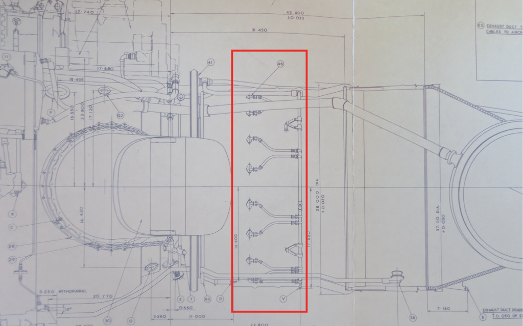
Figure 15: Excerpt of a drawing taken from the Pegasus Mk.101 Installation Guide featuring the water injectors (shown in red box).
Ongoing Research
All projects start with a large amount of research, whether that be finding subject matter experts, 3D scanning airframes, photographing components, or even purchasing reference kits. However, we often need to conduct further research as a project progresses to fill gaps in our knowledge that working on the project has revealed. We’ve had a few instances of that this month that I thought I’d share with you.
One area where we were lacking a bit of information was the Sidewinder missiles and associated pylons/adapters. Nick Greenall was able to guide us on the types used and the variations, but we needed some 3D data which David Jones was able to provide us with via a photogrammetry scan. It may look a bit rough and ready, but it’s in combination with photographs, it really is invaluable to the design team.
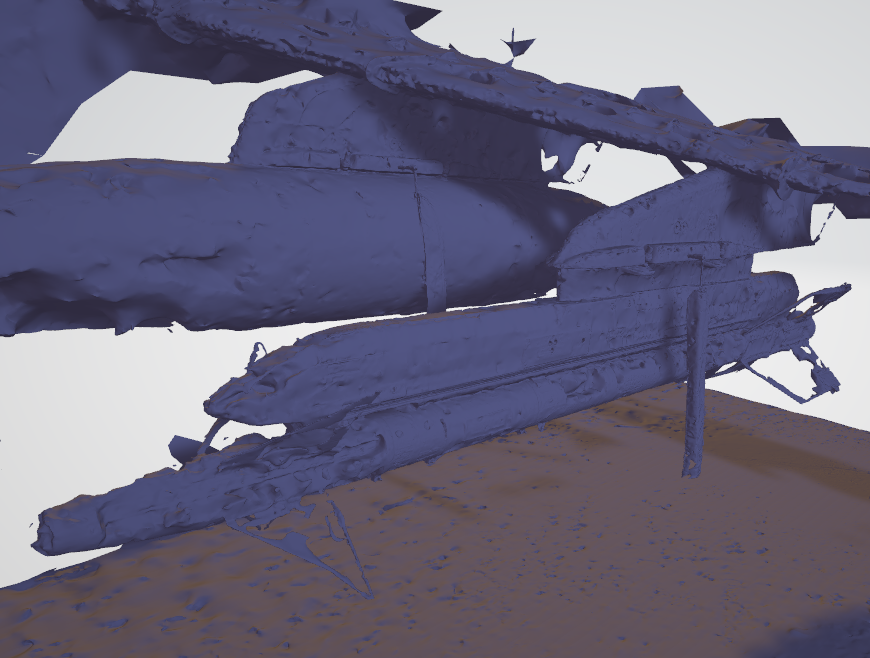
Figure 16: LAU-8 and AIM-9L photogrammetry scan; we also have a scan of an LAU-7 adapter thankfully!
Whilst each video update is filmed in front of a different Harrier, this isn’t reason enough to travel the country on the company’s dime! Every time we visit an aircraft, we’re either taking measurements, photographs or speaking to experts. I recently visited ZD667 at Bentwaters Cold War Museum, which the team have been working on over the past couple of months/years, to record the intro/outro of this month’s video. However, Chris was also after some information to help with his panel lines, especially in places where the 3D scan had not picked up many details. So, armed with a tape measure and a phone, I got to work measuring the access panels located on the nose cone, revealing that they aren’t all the same size and certainly aren’t mirrored on either side, something we could have easily missed!
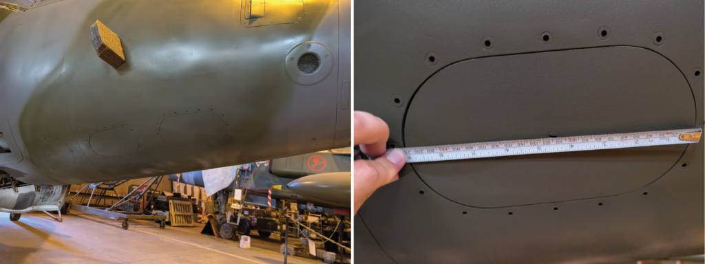
Figure 17: Front access panels on the nose of the GR.3 and the high tech method of measuring them.
We also used the visit to Bentwaters to establish the neutral position of the reaction controls fitted to the Harrier. We had debated how these would look when on the ground or in-flight, but as you can see on the Bentwaters example, this seems to be the ‘neutral’ position:
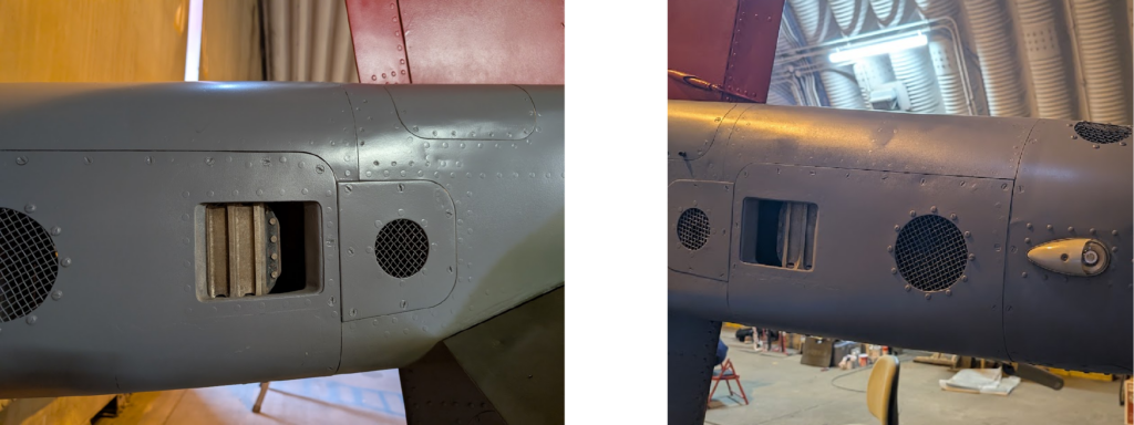
Figure 18: Reaction control nozzles on the tail of the Harrier GR.3.
We were also lucky to find this great video that shows this mechanism (01:50):
“Your Name Here” Competition
As part of our ongoing partnership with the modelling charity Models for Heroes, we have come together to launch a competition to raise funds to help them with the amazing work they do. You can find out more about Models for Heroes here: https://www.modelsforheroes.org.uk/
The prize? One lucky winner will have their name added to the Harrier decal sheet in the form of a pilot/crew name and receive a copy of the kit when released in Q3 2027. Now, it won’t just be added to one decal sheet; the winner’s name will feature on the entire production run!
For more details and to enter, please use this link: https://raffall.com/425233/enter-raffle-to-win-your-name-on-the-new-132-revell-harrier-gr1gr3-hosted-by-modelsforheroes
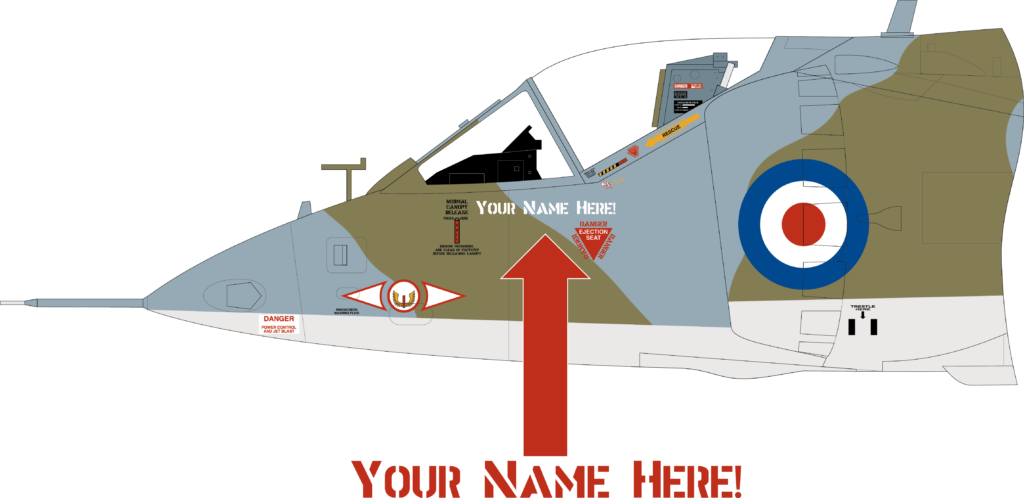
Figure 19: Illustration showing where your name could end up!
Project Harrier on YouTube
As with every update, we have also recorded and released a video update covering much of the same content but with a few differences. So, if you simply can’t get enough of us wittering on about Harrier (pun intended!), then please check the YouTube video out:
What Next?
Over the next month, the design team will continue their work, and we’ll post another update in early October (Friday 2nd). Chris will mainly be focusing on adding rivets to the airframe and sorting out option parts such as aerials and other small details. Horatio will be printing off the engine to confirm aspects of the design and making any necessary changes; however, the bulk of his month will be taken up with the underwing stores.
Around the middle of September, we are hoping to post a series of screenshots of the near-final design for you to look over and provide comments. We’re hoping that we can then make any changes before the next update and, crucially, before we start to cut the moulds!
If you would like to share your knowledge about the Harrier or point out common pitfalls, please send an email to info.de@carrera-revell.com with the subject line “Project Harrier”. I will try my best to read them all and answer them if possible!
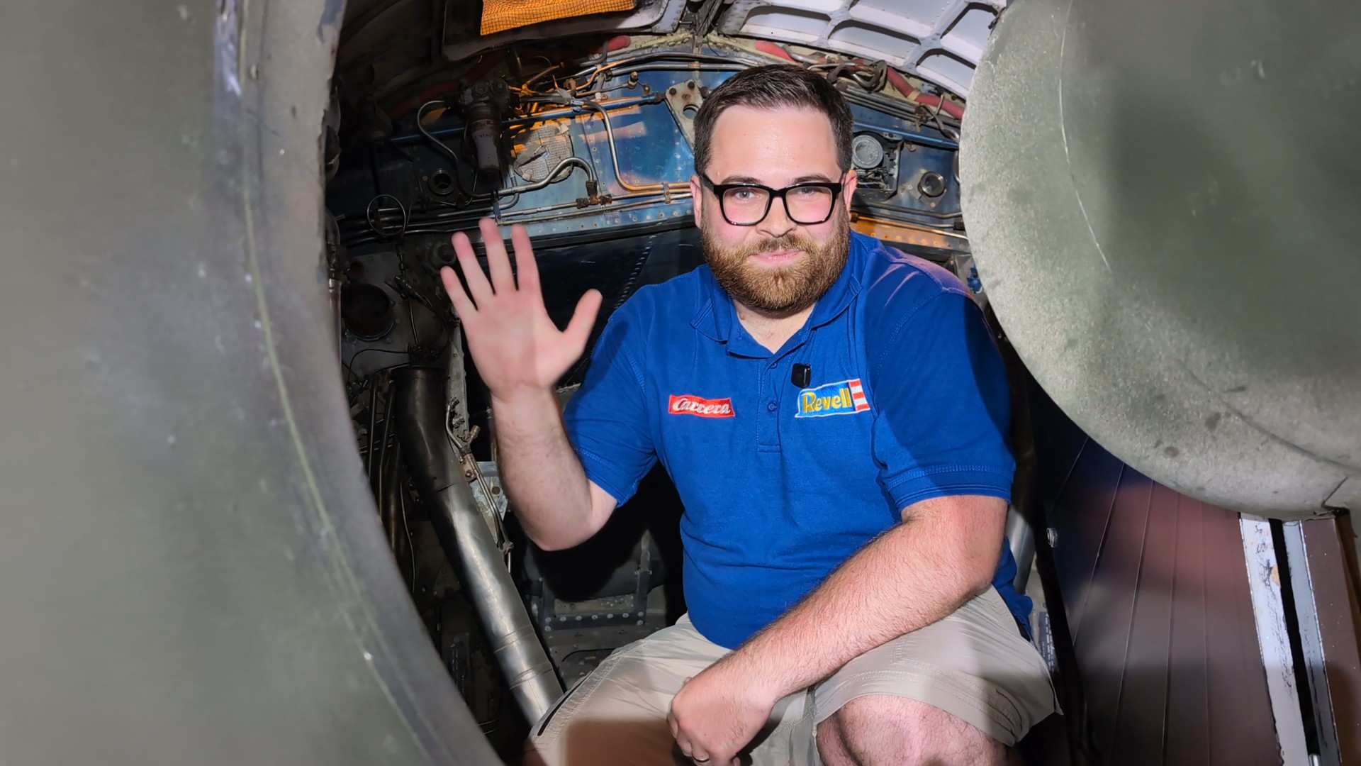
Thank you to Bentwaters Cold War Museum for allowing us to visit earlier this month to record the video update. The plan had been to record in front of the jet, but when the opportunity to film from within the engine bay presented itself, I couldn’t turn it down.
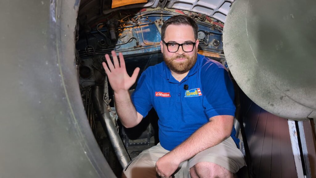
Figure 20: Blog author in the belly of the beast!
As in previous months, Nick Greenall has been providing invaluable support to the whole team, and we count ourselves lucky to have his expertise to rely upon. Thank you, Nick!
Until next time!
Luke