
Hello, and welcome to the fourth instalment of our Project Harrier blog series! For those joining us for the first time, it’s worth reiterating what this is all about. We have begun developing a new 1:32 first-generation Harrier family, with the first boxing being released in Q3 2027.
Rather than design the kit and begin tooling before announcing to the public, we wanted to do something slightly different: bring you along on the development journey and give you a behind-the-scenes look at the processes we go through to deliver a new kit. To that end, we’ll be providing monthly updates using a YouTube video series, blogs such as this one, plus occasional updates via social media and model shows. The blogs and videos themselves will be created by the development team working on the project, so you are hearing it directly from the horse’s mouth!
This month has seen our design team, Chris & Horatio, progress their respective elements of the design even further. Chris has been focusing on the cockpit, seat and undercarriage bays whilst Horatio continued with the Pegasus with the occasional break to focus on underwing stores such as the Matra 155’s, drop tanks, etc.
Airframe Progress
Chris has been working hard on the airframe; the shape is now finalised, and we’re beginning to split parts to allow for future versions. However, panel lines and rivets are still missing; this will be next month’s challenge!
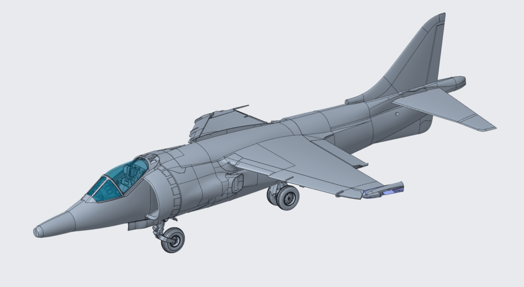
Figure 1: Airframe progress as it stands on 04/08/2026, top view.
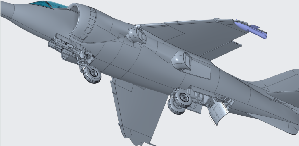
Figure 2: Airframe progress as it stands on 04/08/2026, underside view.
A lot of work has gone into the undercarriage bays with these almost being entirely detailed now. We’ve had to exercise some restraint in these areas as there is a temptation to add every pipe and bit of detail visible (which seems to be never-ending); however, we must always keep an eye on part count and buildability. We want the build to be enjoyable rather than fiddly! And, as I’m sure many of you will be thinking, most of it isn’t visible when displayed owing to it being underneath and inside the airframe.
Aside from the undercarriage and its bays, Chris has been extremely busy with the cockpit and Martin Baker seat. I asked him to prioritise this area so that figure design could begin; a rough outline of the cockpit is needed for this work to start.
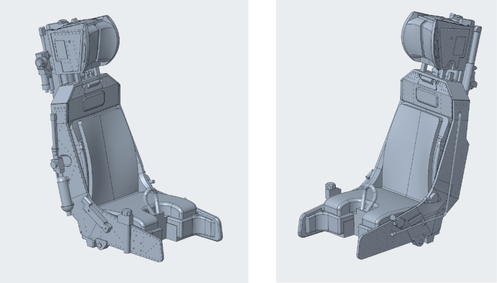
Figure 4: Martin Baker Mk.9A seat design with no fabric effect or seatbelts yet added.
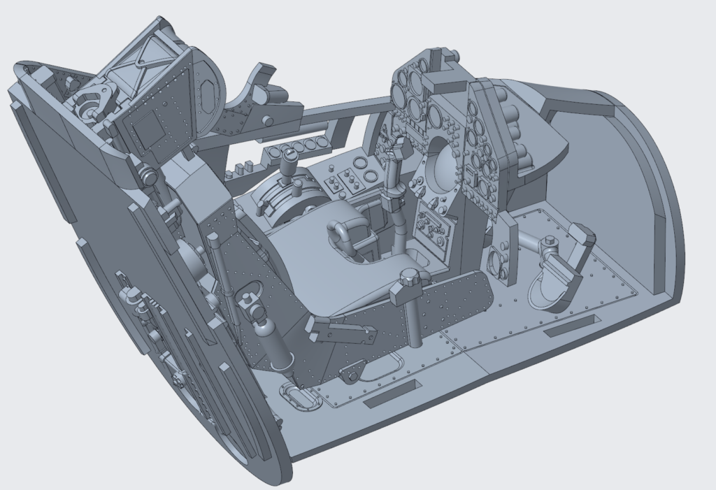
Figure 5: Current cockpit status.
We are now working on the differences for a GR.1 and GR.3 within the cockpit, one of which is the control stick. On a recent research trip, Chris became more excited than he will care to admit when he realised the stick in the cockpit of a GR.3 was in fact from a GR.1, something we had been missing! Out came the camera and through some computer trickery we were able to generate a 3D scan of this part in short order, helping Chris to capture the shape of the early stick.
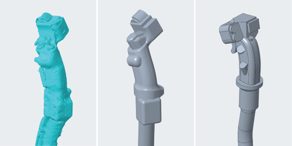
Figure 6: GR.1 Control stick 3D scan (left), initial CAD for the GR.1 stick (centre) and GR.3 stick (right).
We’ve also recently realised that the engine may be able to fit within the jet; we had previously been working under the assumption that the engine would have to be a separate display piece due to the scale thickness of the walls preventing a true-to-scale engine fitting without significant changes to the proportions. However, it appears possible, and we want to keep this option open to any diorama builders out there.
This recent revelation led us to Aerospace Bristol, where they have a Sea Harrier FA2 with the engine removed and the empty bay lit; this allowed us to get photos of this otherwise inaccessible area that will be useful when adding detail. We hope you find these images as fascinating as us!
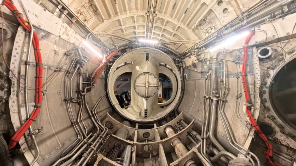
Figure 7: Sea Harrier FA.2 engine bay, facing forwards.
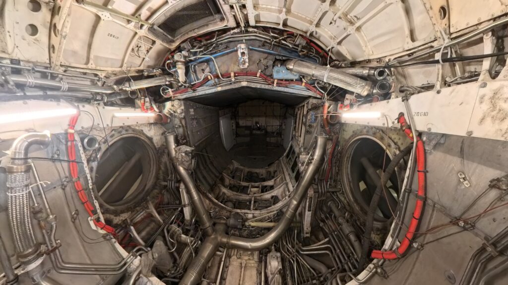
Figure 8: Sea Harrier FA.2 engine bay, facing rearwards.
Pilot Figure
Of course, as with Meteor, we’ll be including a seated pilot figure with this release. Amanda and David (freelance designers) have been busy getting the information needed to craft an accurate pilot with a period-appropriate uniform. This has included 3D scanning a cockpit and even scanning a mannequin in-situ to ensure the figure looks to be seated naturally. It’s worth noting that we have to pick which era to portray, as uniform and seat straps changed over the life of the Harrier. In this case we’ll be showing a pilot from the early ‘80’s with the longer style straps moulded on.
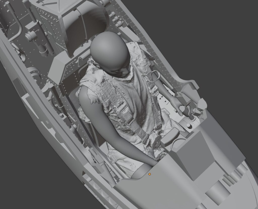
Figure 9: Mannequin placed into the barebones cockpit provided by Chris.
After the initial work, it was realised that the rudder pedals were set fully forward as if for a small pilot, leading to a lack of space for the figure’s legs. We therefore tweaked the position back by 2.25mm so they were in the correct position for an average-proportioned pilot. Some of the flight controls were also altered, namely the throttle, which was moved from idle to a mid-power setting to allow for a more natural stance.
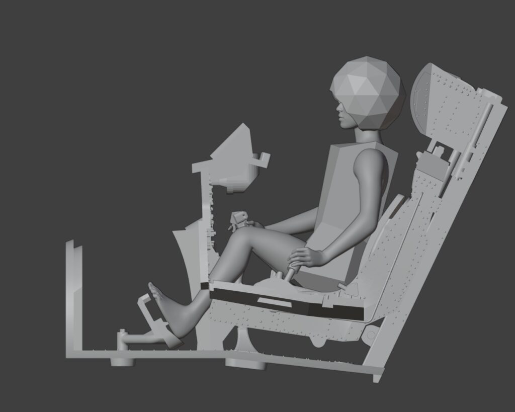
Figure 10: Start of the 3D design of the figure featuring a rough idea of the helmet size and a blocky top to preserve modesty! The issue with the rudder position is evident here with the knees sitting far too high.
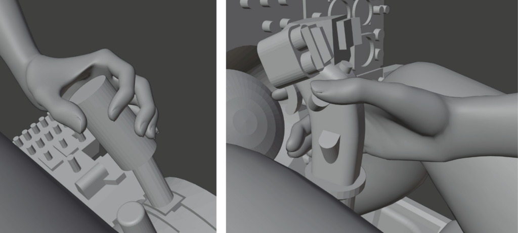
Figure 11: Initial work on the hand positions for the figure.
The pilot figure within the kit will be compromised slightly to allow for injection moulding. However, we also plan to offer a downloadable figure for 3D printing that has not been altered with injection moulding in mind for those that are able to make use of such a file.
Engine Progress
Progress continues to be made on the Pegasus engine, with a large number of small tweaks made to the overall shape and work now focusing on the pipework and control units that sit on top of the engine itself.
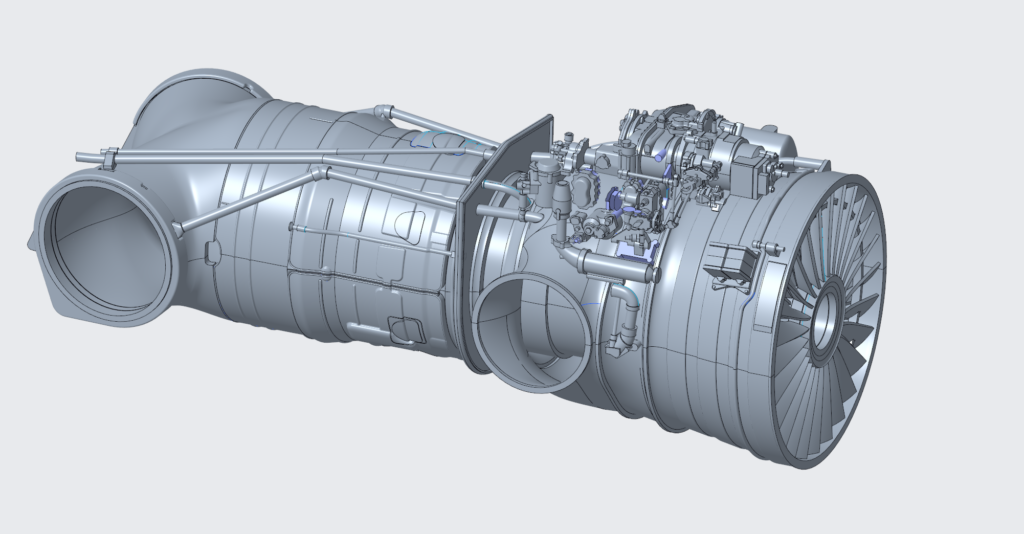
Figure 12: Engine progress as it stands on 04/08/2026.
Luckily, we have a rather detailed scan of the pipework and other elements that sit on top of the engine; Horatio has been using this to accurately position the various parts. However, it’s a slow and laborious process with lots of challenges when it comes to manufacturing constraints. We’re also growing increasingly concerned with the part count; our job is always a tightrope walk of trying to maximise detail whilst also keeping an eye on cost and buildability!
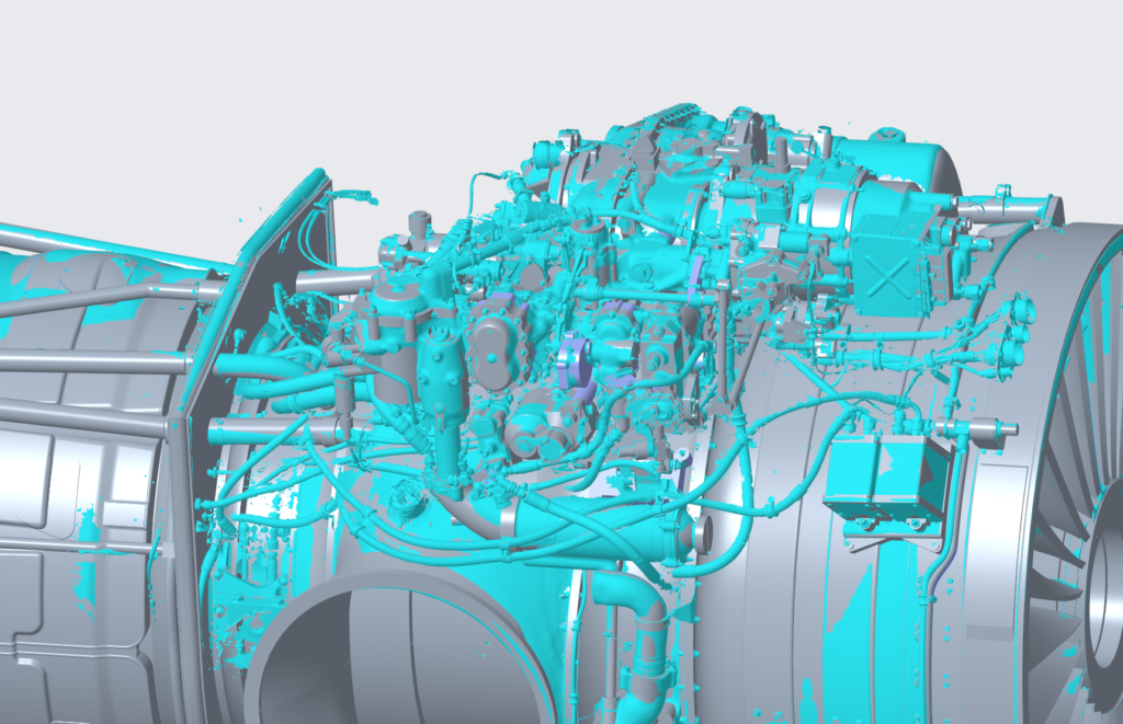
Figure 13: Current design (grey) with the 3D scan overlaid (blue).
Of course, one of the major constraints for us with injection moulding is draft direction and angle. We have to consider what details are more visible and design the parts with this in mind because it often isn’t possible to include detail on all faces of a part without increased cost and complexity. Another pitfall is that the ability to zoom in on parts when designing in CAD is that you lose sight of their exact size. Often, parts can look slightly strange when a draft angle has been added or details omitted, but once you 3D print them, you realise just how little can actually be seen.
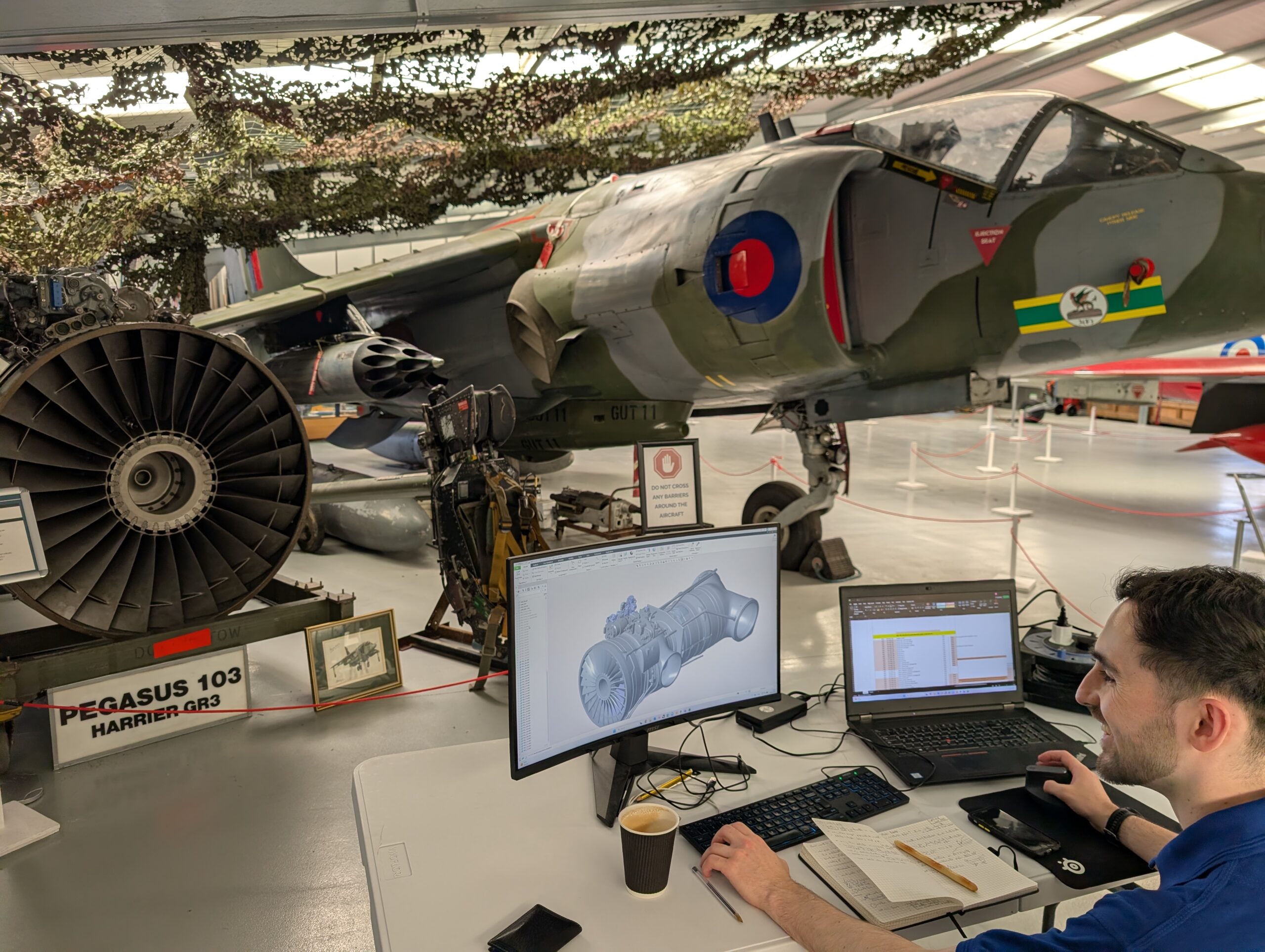
We once again visited Gatwick Aviation Museum for some research but in a rather unusual way this time. Typically, we visit, collect our measurements and photos before returning to the office. However, we thought, why not bring the office to the plane? This means that changes can be made in real time and complicated areas that would require flicking through thousands of images all of a sudden become easier to understand. Plus…it makes for a rather cool view from the office ‘window’!
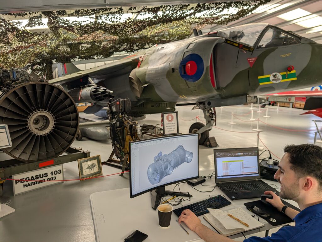
Figure 14: Horatio’s office for the day, not a bad view!
One element we realise we are missing information on was the Gas Turbine Starter that is mounted towards the back of all the control system/pipework on top of the engine. All examples we had seen have this area blanked until we visited Boscombe Down Aviation Collection to film the intro and outro for the video version of this blog, where we found a Pegasus 106 with the starter still fitted! Not only that, but we also had a 3D scanner with us following an unrelated research trip…result! So, we got to work collecting photos and measurements to help Horatio, I’m sure we’ll be able to show more fruits of that work in the September update.
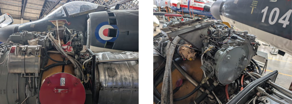
Figure 15: Pegasus 106 featuring the Gas Turbine Starter.
Underwing Stores
In addition to the engine, Horatio has spent a bit of time getting the pylons and the underwing stores progressed. The main focus so far has been the drop tanks and Matra pods, but some work has also been done on the BL755. Most of the work has been surrounding the overall shape and part breakdown of these items with detail to be added at a later date.
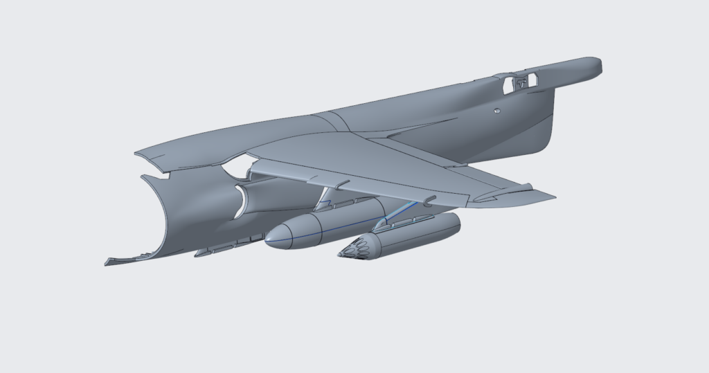
Figure 16: Airframe components stripped back to those relevant and the beginning of the central and wing pylons in addition to the 100-gallon tank and Matra 155 Pod.
Whilst at Gatwick for our research trip, we mainly focused on the complicated pipework on top of the Pegasus but also noticed something on a previous project of ours that would help us on Harrier. Harriers had two main types of the 100-gallon tanks (Metal and Asbestos), but there were also different fins used on these. Most Harriers you see will have the asbestos tanks with no fins fitted; this makes it hard for us to design them accurately.
However, some of you may remember we 3D scanned the Hunter T.7 at the same museum a couple of years ago, and luckily the Hunter used the same tanks as the Harrier, but this example still had the anhedral fins fitted. We were therefore able to take photos and measurements and also use the 3D scan captured in 2024 to get the shape just right.
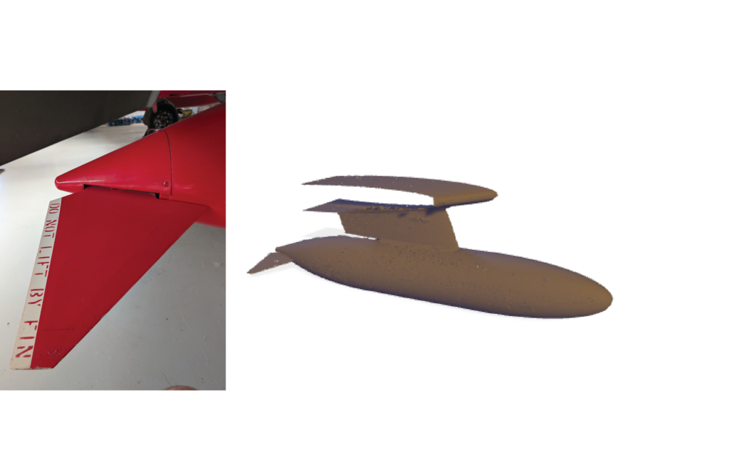
Figure 17: Hunter drop tank fin and 3D scan, as used by the Harrier.
Recent Model Shows
As mentioned at the end of last month’s update, we have attended both the Scale Model South and IPMS Avon shows in the last few weeks. It has been great catching up with all the Revell and Harrier fans. Thank you for all the support and encouragement for our approach on this project; it means a lot to us!
At the Avon show, we were able to display several 3D prints showing where the design’s progress so far alongside a rough model of the whole airframe to illustrate the size of the finished kit. On the morning of the show, we were gifted an original Rolls-Royce installation guide for the Pegasus 101 by Tim Perry; this will be remarkably helpful to Horatio and also take pride of place on my bookshelf!
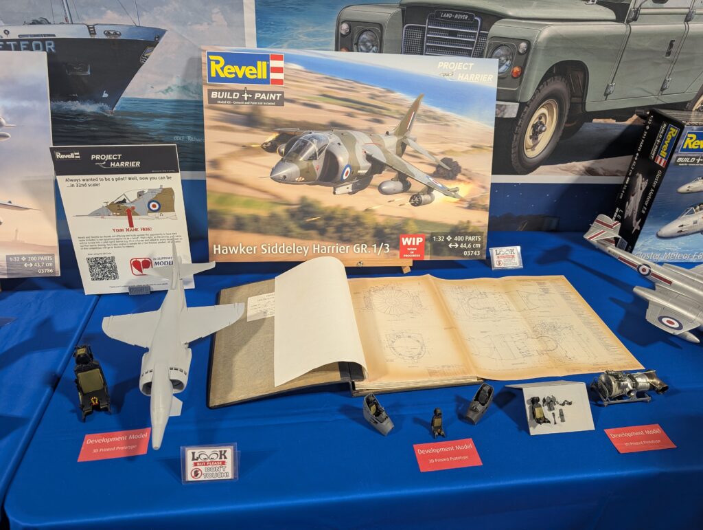
Figure 18: Harrier display at IPMS Avon model show.
“Your Name Here” Competition
As part of our ongoing partnership with the modelling charity Models for Heroes, we have come together to launch a competition to raise funds to help them with the amazing work they do. You can find out more about Models for Heroes here: https://www.modelsforheroes.org.uk/
The prize? One lucky winner will have their name added to the Harrier decal sheet in the form of a pilot/crew name and receive a copy of the kit when released in Q3 2027. Now, it won’t just be added to one decal sheet; the winner’s name will feature on the entire production run!
For more details and to enter, please use this link: https://raffall.com/425233/enter-raffle-to-win-your-name-on-the-new-132-revell-harrier-gr1gr3-hosted-by-modelsforheroes
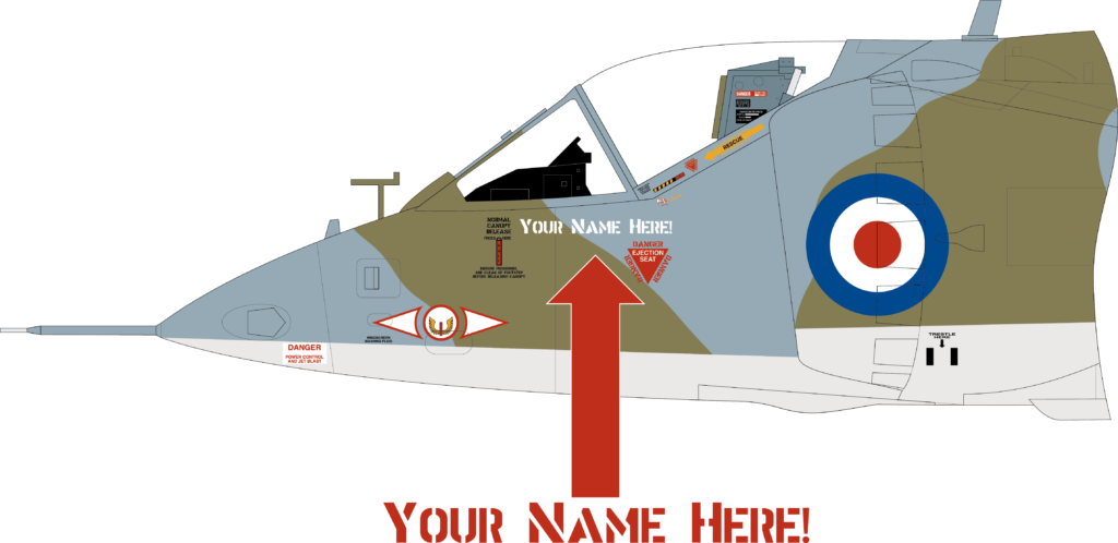
Figure 19: Illustration showing where your name could end up!
YouTube Update
As with every update, we have also recorded and released a video update covering much of the same content but with a few differences. So, if you simply can’t get enough of us wittering on about Harrier (pun intended!), then please check the YouTube video out:
What Next?
Over the next month, the design team will continue their work, and we’ll post another update in early September (4th). Chris will mainly be focusing on adding detail to the airframe in the form of panel lines and rivet detail. Horatio will, hopefully, have the Pegasus engine complete and be well underway with more of the underwing stores, including items specific to the AV-8A. As we’re intending to be done with the design for the ground attack versions by the end of September, in the next update we’ll be presenting the almost finished design and asking for critique before we commit to cutting steel.
If you would like to share your knowledge about the Harrier or point out common pitfalls, please send an email to info.de@carrera-revell.com with the subject line “Project Harrier”. I will try my best to read them all and answer them if possible!
Thank you to Boscombe Down Aviation Collection for allowing us to visit earlier this month to record the video update. As in previous months, Nick Greenall has been providing invaluable support to the whole team, and we count ourselves lucky to have his expertise to rely upon, thanks you Nick! I must also thank both Chris Sargeant and Lee Powell who put together 3D printed prototypes in record time ahead of our appearance at the IPMS Avon show. Finally, another thanks to Gatwick Aviation Museum for allowing us to visit once again.
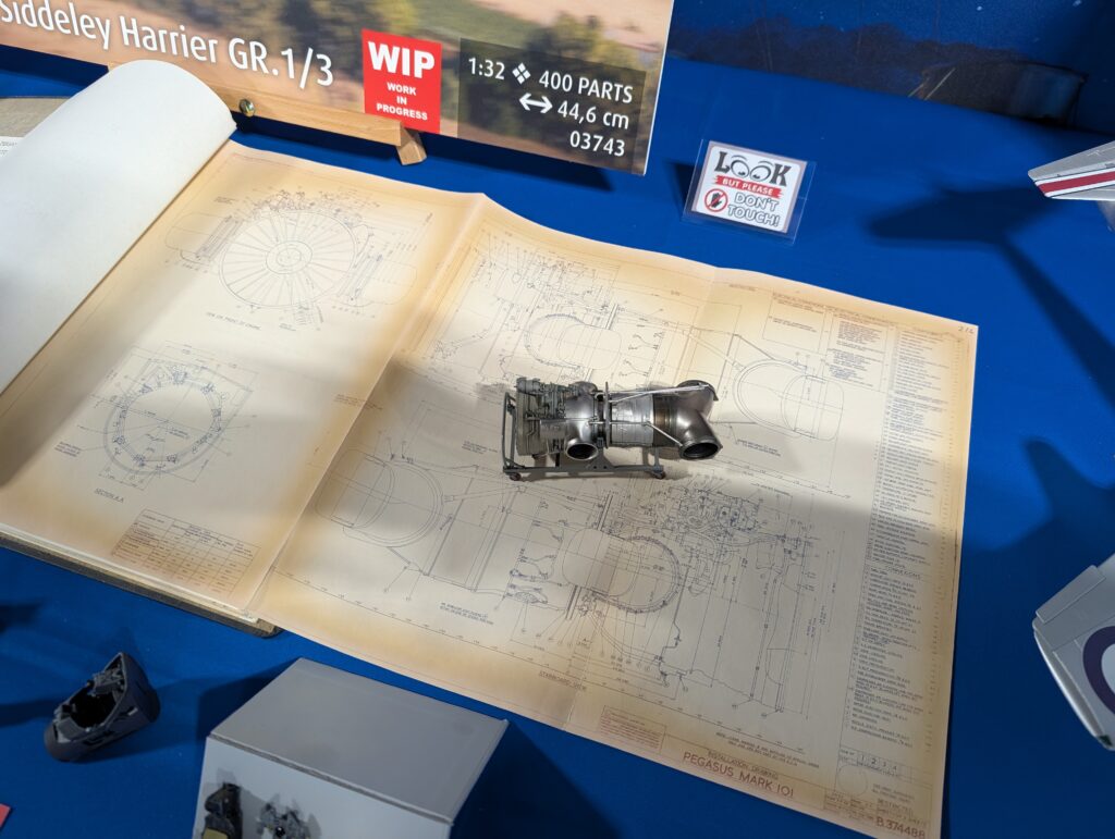
Figure 20: Chris Sargeant’s fantastic build of our Pegasus 103 model (development model) on top of a Pegasus installation guide drawing.
Until next time!
Luke